




 Request Quote



Scrap Car Recycling Plant Layout: Zones, Flow and Equipment
The layout of the scrap recycling plant is not just the drawing of the machine on the floor.This is a decision about how the vehicle enters the scene,where to remove the dangerous parts,how to prepare the hull in stages,and how the broken metal moves through the recovery of black and non-ferrous metals without causing traffic,safety or maintenance problems.
Quick Answer
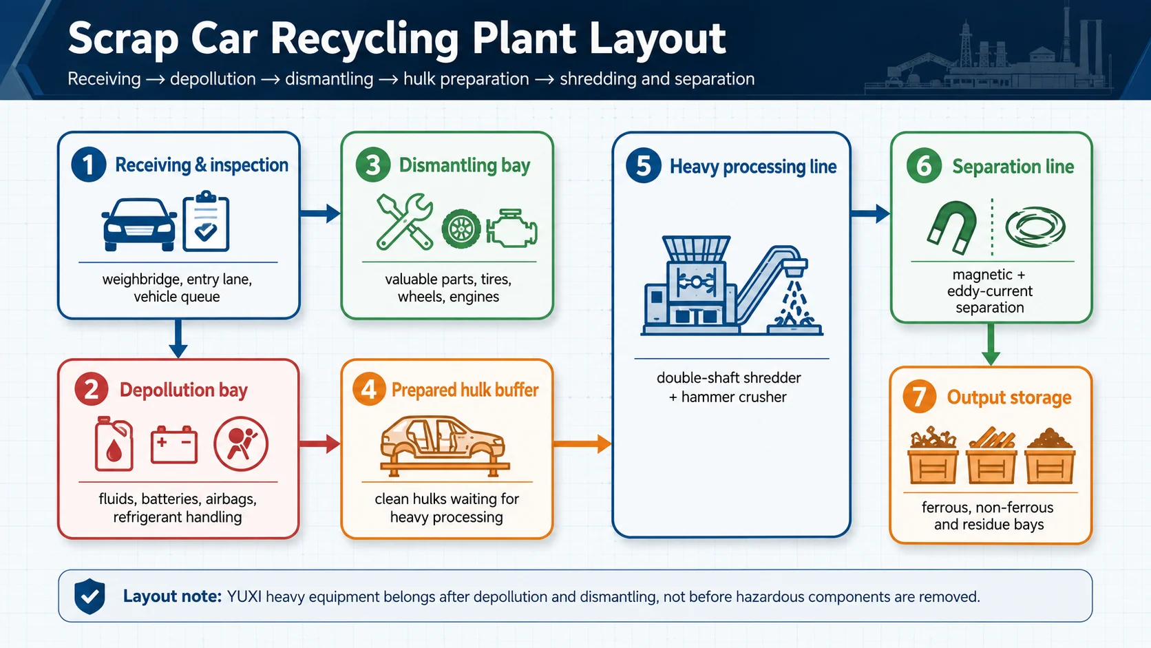
A good lay out of the scrap recycling plant usually follows the follwing order: vehicle receipt, inspection, decontamination, disassembly, prepared h storage, primary shredding, secondary crushing, magnetic separation, vortex separation, residue treatment and separated product storage. Heavy-duty shredded paper pipes should only receive prepared vehicle shells or metal parts after liquids,batteries,refrigerants,airbags and other controlled items are removed according to local rules.
For the YUXI project, the actual layout problem is usually:: how should the buyer link the pollution removal and demolition work with the downstream scrap recycling line using double-shaft crushers,hammer metal crushers,magnetic separators,vortex separators and centralized control systems?The answer depends on the feeding conditions,daily volume,required output,processing equipment,bulding size,power supply,dust control and maintenance gaps.
1. Define the Layout Boundary Before Drawing the Line
The first mistake is treating a scrap car recycling plant as one long conveyor. End-of-life vehicles are not uniform raw material. They can include fuel, oil, brake fluid, coolant, refrigerant, batteries, airbags, tires, glass, plastics, interior, reusable parts and valuable non-ferrous parts. Therefore,the complete layout must separate two different jobs.
The first job is vehicle treatment: receiving, documentation, depollution, dismantling and preparation. The second job is metal recovery: reducing prepared shells or metal parts into a sortable stream and recovering ferrous and non-ferrous metals. The European Union’s ELV summary describes end-of-life vehicles as being stripped before further treatment, with hazardous substances and components removed and separated. It also sets reuse/recycling and reuse/recovery targets for vehicle design and treatment policy. EUR-Lex source
That boundary matters commercially. If a buyer asks only for a shredder layout but plans to receive complete vehicles, the project is incomplete. The site still needs safe areas for drainage, battery handling, airbag or pyrotechnic component management, refrigerant recovery where applicable, reusable parts storage, and waste storage. The downstream shredder line cannot solve those pre-treatment obligations by itself.
2. Where the YUXI Waste Car Recycling Line Fits
YUXI’s published waste car recycling line is positioned for scrapped vehicles and waste metal parts such as car shells, bumpers, engine casings, carriage boards, motors, wheels, motorcycles and bicycles. The page describes a working process built around a double-shaft crusher for primary shredding, a scrap hammer-type metal crusher for deeper crushing, magnetic separation for iron metals, eddy-current separation for non-ferrous metals and a centralized control system.
For layout planning, this means the YUXI line should be treated as the heavy processing and separation section of the facility. It is not the whole authorized treatment yard by itself. The buyer still needs upstream receiving, depollution and dismantling areas; downstream metal storage and residue handling; and enough access around every machine for loading, maintenance, blade or hammer inspection, belt service and emergency stops.
The product-page information is useful for deciding the process order. Primary shredding handles bulky prepared shells or metal parts. Secondary crushing improves liberation when the material must become more suitable for sorting. Magnetic separation first removes iron-rich material. Thwn,the eddy current separates aluminum, copper and other conductive non-ferrous metals that do not respond to ordinary magnets. The control system should be placed where operators can monitor feeding, machine load, conveyor transfer points and discharge quality without standing in danger zones.
3. Core Zones in a Scrap Car Recycling Plant Layout
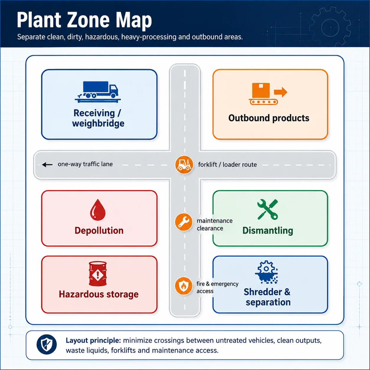
A clean layout is built from zones, not from isolated machines. Each zone should have a purpose, a traffic rule and a storage limit. When these are unclear, vehicles wait in the wrong place, forklifts cross the shredder loading route, hazardous items are mixed with ordinary scrap, and maintenance work becomes difficult.
Receiving and inspection zone
This zone should handle entry control, vehicle identification, weighing, visual inspection and temporary staging. It should not be crowded with product storage or heavy maintenance work. The receiving route needs enough turning space for tow trucks or carriers and should prevent untreated vehicles from blocking outbound scrap trucks.
Depollution zone
Depollution needs a controlled floor, fluid collection logic, fire-aware storage and a work sequence that prevents accidental mixing of liquids and components. New York State’s vehicle dismantling facility guidance notes that facilities may generate refrigerants, oil, transmission fluid and components such as mercury switches, lead-acid batteries and PCB capacitors, and that these concerns sit alongside stormwater, hazardous waste, air emissions and petroleum spill issues. NYSDEC source
Dismantling and reusable-parts zone
After depollution, operators may remove engines, wheels, catalytic converters, aluminum parts, wiring, radiators, reusable components or other saleable items depending on the business model and local law. This zone needs benches, lifting or tilting support, part racks, bins, safe walkways and a route to move prepared shells forward.
Prepared hulk buffer
A buffer between dismantling and heavy processing protects the shredder from irregular supply. It also gives operators a place to reject vehicles that are not ready. This buffer should be clearly marked as “prepared material only,” especially when the site receives complete vehicles and prepared hulks at the same time.
Shredding and crushing zone
This is the high-energy area. It needs loader or grab access, hopper visibility, guarding, noise and dust planning, power supply, service walkways and a method for handling jams. It should not be placed in a tight corner simply because the machine fits on paper. Maintenance access is part of the footprint.
Separation and product storage zone
After size reduction, material must move through magnetic separation, eddy-current separation and storage bays without cross-contamination. Ferrous waste, non-ferrous metals and residues should be stored in separate areas. A clean storage plan makes buyer inspection easier and helps operators notice quality problems quickly.
4. Material Flow: The Layout Should Reduce Crossings
The most reliable plant layouts use a one-way material flow. Untreated vehicles enter from one side. Depolluted and dismantled hulks move forward. Shredded material continues through separation. Clean outputs leave from the opposite side or a separate outbound route.It sounds simple, but many layouts fail because trucks, forklifts, loaders and people share the same space.
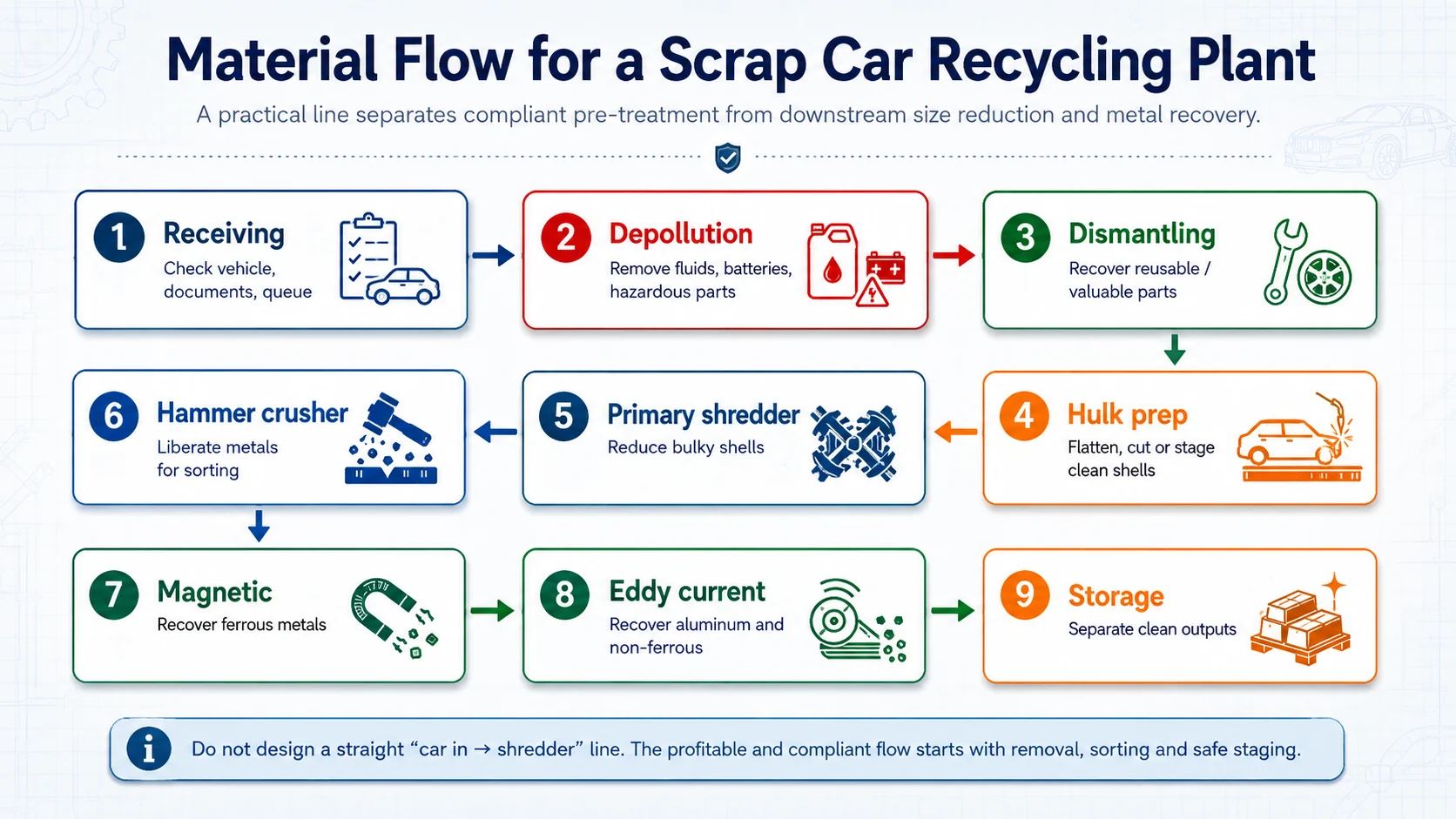
Try to separate four flows: vehicle flow, hazardous-material flow, heavy-material flow and people flow. Vehicle flow includes receiving, staging and movement to depollution. Hazardous-material flow covers fluids, batteries, refrigerants and controlled parts. Heavy-material flow covers prepared hulks, shredded material and product piles. People flow includes operators, maintenance technicians and visitors. The fewer crossings between these flows, the easier the plant is to manage.
Plant owners should also plan for reverse flow. Sometimes a hulk is not ready, a feed piece is oversized, a conveyor needs cleaning, or a separated product pile fails quality inspection. If the only route is forward, operators improvise. A good layout includes reject areas and rework paths that do not block normal production.
5. Equipment Placement by Process Stage
Equipment should be placed according to process consequence, not only according to available floor area. A machine that is difficult to access will cost time every time it needs inspection, cleaning, blade or hammer work, belt adjustment or sensor checking.
Double-shaft crusher / primary shredder
The primary shredder should be close enough to the prepared hulk buffer for efficient feeding, but not so close that storage piles spill into the service area. It needs a safe loading side, a discharge side that lines up with the next conveyor, and enough surrounding clearance for maintenance. If a grab crane or loader feeds the machine, the machine position must match swing radius, visibility and operator protection.
Hammer-type metal crusher
Secondary crushing is normally placed after primary shredding when better liberation or smaller material is needed before separation. The layout should consider dust, noise, inspection access, wear-part replacement and the route for tramp or unsuitable material. Do not place a hammer crusher where blocked discharge can back up into the primary shredder.
Magnetic separator
What the material is presented in the controlled layer,the magnetic separation effect is the best. The conveyor that conveys the magnet should not be overloaded or uneven. Leave room for ferrous discharge, product bay cleaning and magnet maintenance. If ferrous material falls into the wrong pile, operators need space to correct the problem safely.
Eddy-current separator
The vortex separator should be carried out after removing the black metal,because the remaining iron-rich parts will interfere with the recovery of -non-ferrous metals and equipment. The layout should include adjustable separartors, separate trash cans for non-ferrous and residual flows, and space for quality inspection. Since aluminum and copper value often justifies this stage, the discharge bays should be protected from accidental mixing.
Central control and observation
The control cabinet or control room should not be placed only for cable convenience. Operators need line visibility, safe access, dust protection and a practical route to inspect alarms. YUXI’s product page mentions centralized control for monitoring the line; in layout terms, that control point should support quick decisions about feeding, overload reversal, conveyor stoppage and product quality.
6. Space, Utilities and Access: Do Not Quote From Footprint Alone
A drawing that shows only machine length and width is not a plant layout.The actual footprint includes feeding space, inventory space, maintenance door, belt replacement route, dust removal equipment, electrical cabinet, safe sidewalk, emergency passage, fire lanes drainage, truck turning radius and future expansion. These items will take up more space than the machines themselves.
| Layout factor | What to verify | Why it changes the design |
|---|---|---|
| Building size | Clear length, width, height, columns, doors and crane coverage | A machine may fit, but feeding and maintenance may not. |
| Feed method | Grab crane, loader, forklift, conveyor or manual staging | Controls hopper position, safety fencing and traffic direction. |
| Power supply | Voltage, transformer capacity, cable route and cabinet location | Heavy equipment and separation systems need stable electrical planning. |
| Dust and air | Collection points, piping routes, filters and emission control | Dust equipment cannot be added as an afterthought in a compact layout. |
| The maintenance | Channel of blades, hammers, belts, bearings, hydraulic and electrical services | Insufficient gaps turn daily services into production shutdowns. |
| Output logistics | Ferrous, non-ferrous and residue bays plus truck loading routes | Good separation loses value if clean products are mixed again in storage. |
Exact plant dimensions should be confirmed with YUXI’s engineering team after the buyer provides the site drawing, material photos or videos, desired capacity, local safety requirements and output targets. Without that information, any footprint number is only a rough concept and should not be treated as a final layout.
7. Safety and Maintenance Must Be Drawn Into the Layout
Scrap car recycling equipment has moving conveyors, rotating shafts, crushing chambers, hydraulic systems, exposed material edges and heavy loading equipment. OSHA’s general machine guarding rule states that machine guarding should protect operators and other employees from hazards such as point of operation, ingoing nip points, rotating parts, flying chips and sparks. OSHA 1910.212 source
Maintenance layout is just as important. OSHA’s locking/marking standards cover the service and maintenance of accidental power-up,start-up or release of stored energy that may harm workers.It requires procedures to disable equipment and control hazardous energy sources. OSHA 1910.147 source
In the actual layout, this means that emergency stations, isolation points, security gates, service platforms, lighting and security passages should be discussed before installing the equipment. A conveyor that is easy to draw but impossible to clean safely will become a daily problem. A shredder that cannot be accessed by service tools will increase downtime. A control cabinet placed in a dusty, vibrating or blocked area will reduce reliability.
8. Common Layout Mistakes Buyers Should Avoid
Mistake 1: Starting from the shredder
The shredder is important, but the layout should start from incoming material, pre-treatment requirements and product flow. Otherwise the line may be powerful but difficult to feed.
Mistake 2: Mixing treated and untreated vehicles
Prepared shells should not be stored in the same uncontrolled pile as vehicles waiting for depollution. Use clear staging rules and visual separation.
Mistake 3: Ignoring output storage
Ferrous scrap, aluminum-rich material and residue need separate bays. If products mix after separation, recovery value is lost.
Mistake 4: Leaving no service space
Machines need space for inspection, lifting, belt service and wear-part replacement. Tight layouts often look cheaper until the first major maintenance stop.
Mistake 5: Forgetting dust, noise and fire planning
Plant layout should reserve space for dust collection, safe storage, fire access and local compliance measures. These cannot always be added later.
Mistake 6: Asking for a quote without site data
A supplier cannot design a reliable layout from the phrase “scrap car recycling plant” alone. Feed condition, target output and site constraints control the answer.
9. Three Typical Layout Directions
Not every buyer needs the same factory. The correct design depends on whether the enterprise mainly makes money from parts,black waste,non-ferrous recycling or integrated processing.
Parts-focused dismantling yard
This layout gives more space to receiving, depollution, lifting stations, parts storage and inventory management. Heavy shredding may be outsourced or added later. It is suitable when reusable parts and components are the main business.
Prepared-hulk shredding and separation line
This layout is centered on heavy material flow. Prepared shells or metal parts are staged, shredded, crushed and separated. It is the closest match for a YUXI waste car recycling line, provided upstream depollution and dismantling are already handled.
Integrated ELV recycling plant
This layout combines receiving, depollution, dismantling, prepared hulk buffer, shredding, separation and product storage in one site. It offers more control, but it also requires stronger planning for compliance, labor, utilities, storage, traffic and safety.
10. RFQ Checklist for a Real Layout Proposal
Before asking for a plant layout, prepare the following information. It allows YUXI to discuss a practical equipment route without inventing capacity, footprint or output assumptions.
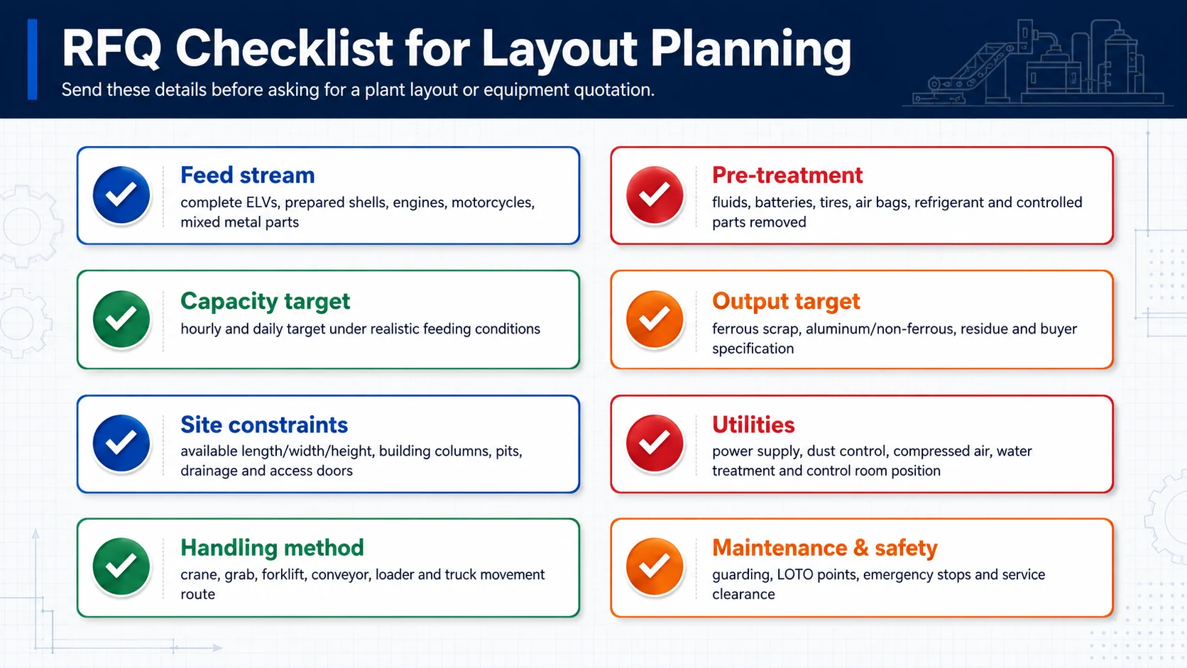
- Photos or videos of the incoming vehicles, shells and metal parts.
- Whether vehicles are complete ELVs or already depolluted prepared hulks.
- Daily and hourly processing target under realistic feeding conditions.
- Required output: rough shredded scrap, cleaner ferrous scrap, aluminum-rich non-ferrous fraction or further refined material.
- Available building or outdoor site dimensions, including height and column positions.
- Preferred feeding method: loader, grab crane, forklift, conveyor or mixed handling.
- Power supply, control room preference, dust-control requirement and local environmental rules.
- Space reserved for maintenance, output storage, truck loading and future expansion.
Need a YUXI layout discussion?
Send material photos or videos, site dimensions, target capacity, desired output and local compliance constraints. YUXI can then discuss whether a waste car recycling line, standalone shredder section or wider plant configuration is the better fit.
Request a layout consultationFAQ: Scrap Car Recycling Plant Layout
What is the best layout for a scrap car recycling plant?
The best layout usually uses one-way flow: receiving, depollution, dismantling, prepared hulk storage, shredding, crushing, separation and clean output storage. The exact layout depends on site size, feed condition, output target, handling equipment and local regulations.
Can a complete car be fed directly into a shredder?
A prepared hulk may be suitable for heavy processing after controlled materials are removed, but untreated complete vehicles should not be treated as direct shredder feed. Liquids,batteries,refrigerants,airbags and other controlled components must first be handled according to local requirements.
How much space does the car recycling line need?
There is no reliable universal footprint. Space depends on machine configuration, feeding method, stockpile size, maintenance clearance, output bays, dust control, truck access and whether depollution and dismantling are included on the same site.
Where should magnetic and eddy-current separators be placed?
They are usually placed after shrinking the size. Magnetic separation removes iron-rich material first. Eddy-current separation is usually used to recover aluminum and other conductive non-ferrous metals from the remaining flow.
What information need to send before requesting a layout?
Send feed photos or videos, whether material is complete or prepared, target capacity, required output, site dimensions, power supply, handling method, local compliance limits and any preferred storage or truck-loading arrangement.
References and Source Notes
- EUR-Lex summary of Directive 2000/53/EC: ELV stripping, hazardous component removal and reuse/recycling/recovery policy context. Source
- New York State DEC vehicle dismantling facility guidance: examples of fluids and components generated by dismantling facilities. Source
- OSHA 1910.212: machine guarding concepts used for safety planning. Source
- OSHA 1910.147: lockout/tagout concepts used for maintenance access planning. Source