




 Request Quote



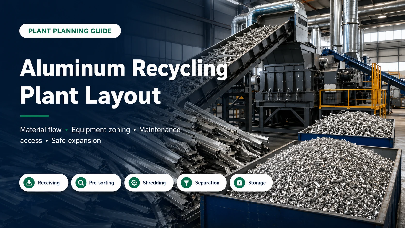
A buyer once sent us a workshop drawing with every machine packed tightly against the wall. On paper, the line fitted. In practice, there was no room to remove a screen, lift a rotor component, turn a forklift, or isolate one product bay from another. The equipment list was reasonable. The layout was not.
That distinction matters. An aluminum recycling plant may lose several hours without a major machine failure,just because materials must be moved backward, loaders pass through manual work areas, finished aluminum is stored beside incoming scrap, or maintenance requires moving several other machines first.
Why Plant Layout Should Be Decided Before Equipment Installation
The public YUXI scrap aluminum recycling line page makes an important point: aluminum profiles, mixed scrap, light sheets, cans, chips, wheels and castings should not be forced through one fixed process. The same principle applies to layout. A profile-shredding line needs different receiving and feeding space from a chip briquetting route. A baling operation needs clean sorting and dispatch access, while a mixed-scrap line needs more room for quarantine, size reduction, reject handling and product sampling.
The U.S. EPA describes secondary aluminum pretreatment as sorting and processing waste to remove contaminants and prepare downstream recycled materials. It also points out that factory steps may be combined or reordered according to waste quality, source, available equipment and product specifications. That is a process statement, but it is also a layout rule: the physical plant must follow the real feed and required output rather than a generic line diagram.
In our experience, most layout problems appear after commissioning. Operators compensate by creating temporary piles, parking bins in aisles, carrying residue across the main route, or leaving service doors blocked because the planned space was too narrow. Those workarounds look minor for the first week. Six months later, they become the normal operating method.
Start With a Layout Design Basis, Not a Building Outline
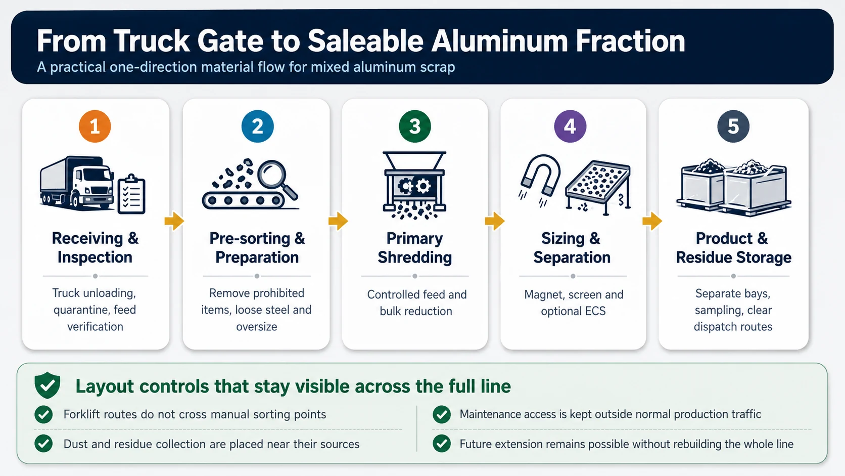
A workshop drawing is only useful after the project basis is defined. Sometimes buyers begin with a building length and ask how many machines can fit inside. We normally reverse the question: what material must enter, what saleable products must leave, and what must happen between those two points?
Incoming material
Record the largest piece, bundle condition, bulk density, moisture, attached steel, non-metal contamination, loading method and prohibited items. Long profiles and low-density foil occupy space differently from dense castings.
Required output
Define reduced scrap, cleaner mixed aluminum, bales, briquettes or sensor-sorted fractions. Product bays, sampling points and residue routes depend on this decision.
Operating pattern
State working hours, truck frequency, loader type, manual sorting level, bin-change method, planned maintenance and expected seasonal peaks.
One customer may need a compact line that processes one stable feed. Another receives demolition frames, cast housings and mixed production offcuts on the same day. The second site needs more quarantine and sorting space even if both projects quote the same nominal throughput.
Information that should exist before the first layout drawing
- Site boundary, building columns, door positions, floor levels and usable ceiling height.
- Confirmed equipment general-arrangement drawings, not catalogue thumbnails.
- Feeding and discharge elevations, conveyor angles and transfer-point geometry.
- Loader, forklift, crane or grab dimensions and turning envelopes.
- Maintenance requirements: screen removal, shaft or rotor lift-out, blade access and service-platform reach.
- Electrical supply, cable routes, compressed air, water or drainage where applicable.
- Product, ferrous, residue and fines container sizes plus the replacement method.
- Local fire, environmental, building, noise, dust and occupational-safety requirements.
The Core Zones in an Aluminum Recycling Plant
1. Receiving and quarantine
This is where the plant gains control of the feed. Provide room for truck unloading, initial inspection, weighing or recording, and temporary isolation of material that does not match the agreed specification. Sealed containers, pressure vessels, batteries, liquids, flammable items and unknown hazardous residue should not be allowed to move directly into the processing area.
Quarantine space is easy to remove from a drawing because it does not produce revenue. Surprisingly, it is one of the areas operators miss most when feed quality changes.
2. Raw-material storage
Separate profiles, mixed scrap, sheets, castings and chips when their process routes differ. Storage bays should not block fire access, emergency exits, electrical rooms or marked vehicle lanes. Material piles also need enough working room for the loader to approach without pushing scrap into walkways.
3. Pre-sorting and preparation
Locate manual inspection before the main shredder, with safe access and a clear reject path. Depending on the feed, this zone may remove loose steel, rubber, wood, glass, valves, tires, bearings, trapped liquids or oversize pieces. The point is not to sort everything by hand. It is to prevent avoidable hazards and protect downstream equipment from material outside the confirmed feed.
4. Controlled feeding
The feed hopper and conveyor should connect the loader to the first process stage without creating blind corners or forcing workers between moving equipment. Long profiles may bridge or tangle, so the approach angle and hopper opening matter. Thin scrap may require a different containment method. Leave room to clear a bridging event under the approved isolation procedure rather than designing a space that encourages improvised access.
5. Shredding and secondary reduction
For bulky profiles, frames and mixed light scrap, the primary size-reduction stage is usually the largest maintenance zone. The layout should show the actual service side of the metal shredder, access to the drive and hydraulic system where fitted, removal paths for screens or shafts, and the lifting method for heavy components.
A secondary hammer mill metal crusher may be added when more liberation or a smaller controlled range is required. That machine changes the layout substantially: it introduces another transfer point, more inspection and wear access, a possible recirculation loop, and additional dust-control demand.
6. Separation and quality control
After size reduction, the plant may use magnetic removal, screening and an optional eddy current separator. Do not squeeze these machines into the last available corner. Stable feeding, suitable particle presentation and clean discharge separation are part of their performance.
Provide a reachable sampling point after each critical separation stage. Operators should be able to inspect ferrous reject, aluminum product and non-metal residue without climbing over conveyors or opening a guard during operation.
7. Finished-product and residue storage
Keep saleable aluminum away from incoming mixed scrap and residue. Product bays should support weighing, sampling, bin or bag replacement and dispatch. Ferrous material, fines and non-metal residue need their own routes. When these streams share one narrow aisle, cross-contamination and traffic delays become normal.
Arrange the Plant Around One-Direction Material Flow
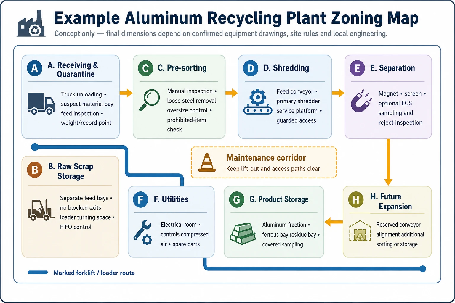
The shortest distance between machines is not always the best. A transfer can be slightly longer and still perform better if it creates a stable material layer, gives operators a clear inspection point, and keeps the discharge away from forklift traffic.
- Bring trucks to the receiving side, not through the finished-product area. Incoming material is the least predictable stream and should be contained early.
- Move suspect material sideways into quarantine. Do not send it backward across the unloading route.
- Feed the processing line in one direction. Avoid conveyor loops that cross walkways or send oversize material through the main traffic lane.
- Split saleable product and residue before storage. Their bins should be replaceable independently.
- Let product leave from the opposite side where possible. This reduces interaction between receiving vehicles and dispatch vehicles.
That is not always possible in an existing building. When the plant must use a U-shaped line, the two ends should still be physically separated. Incoming scrap should not share the same floor space as inspected finished aluminum simply because the building has one large door.
Layout Priorities for Different Plant Scales
| Plant type | Typical layout priority | Common compromise to avoid |
|---|---|---|
| Small workshop | Compact one-direction route, disciplined feed storage, movable bins, clear manual inspection area and realistic maintenance access | Packing machines wall-to-wall and using the only aisle for scrap, operators and product bins |
| Medium recycling plant | Separate receiving, processing and dispatch; defined loader routes; modular conveyors; product and residue bays; central controls | Adding conveyors without confirming transfer height, bin replacement or dust extraction |
| Industrial facility | Parallel feed bays, redundancy where justified, dedicated maintenance area, overhead lifting plan, utility corridors, fire separation and future line extension | Building a high-capacity line with no buffer storage, no bypass strategy and no space for additional sorting |
A small site does not need a miniature version of a large plant. It needs fewer movements and tighter operating discipline. A large site should not simply stretch the conveyor distances. It should use the space to separate risk, create buffers and make maintenance faster.
How Much Space Should Be Reserved Around the Equipment?
There is no universal square-meter figure that can be recommended responsibly. Total plant area depends on the process route, site constraints, machine footprints, transfer equipment, structural supports, walkways, loader paths, storage, control rooms, utilities, maintenance access and safety clearances.
Use four envelopes for every machine
Operating envelope
Normal access for observation, adjustment, sampling, bin replacement and housekeeping while guards remain in place.
Maintenance envelope
Space to open doors, remove screens, service drives, lift components and position tools or a mobile crane after energy isolation.
Material envelope
Hopper loading, discharge trajectory, conveyor transfer, oversize recirculation and temporary buffer volume.
Safety envelope
Guarding, restricted access, emergency-stop reach, egress, marked aisles and the separation of people from mobile equipment.
We have found that the maintenance envelope is the first one removed when the drawing becomes crowded. That saves floor area only until the first major service. Then the plant pays for the missing space with extra labor, dismantling and downtime.
Check vertical space as carefully as floor space
Conveyor discharge height, dust ducting, service platforms and lifting clearance can make a line impossible even when it fits on the floor plan. Confirm roof trusses, crane beams, lighting, sprinklers, pipes and cable trays. Also check whether a forklift or mobile lift can reach each service point without crossing a protected conveyor zone.
Plan the floor and foundations
Heavy fixed machinery should be anchored and the floor must support intended loads. The exact foundation design belongs to qualified local engineers using confirmed machine loads, dynamic forces and soil or slab information. Do not finalize foundations from a preliminary marketing layout.
Utilities, Dust Collection and Control Rooms Need Their Own Layout
Electrical and control location
Place the electrical room where it remains clean, dry, accessible and protected from loader impact. Cable routes should reach each machine without creating trip hazards or making future extension impossible. Operators need a clear view of critical feed and transfer points, but the control position should not sit inside a vehicle turning area.
Dust and fines
Shredding, secondary crushing, screening and transfer points can release fines. The layout should identify each source, duct route, collection point and safe clean-out method. A long, improvised duct run added after installation usually means poorer capture and difficult maintenance. Combustible-dust and fire risks must be assessed for the actual feed, particle size, contamination and collection system under local requirements.
Drainage and wet material
Machining chips or wet scrap require a dedicated liquid-control route. OSHA’s walking-working-surface rules require work areas and passageways to be maintained in a clean and, as far as feasible, dry condition; where wet processes are used, drainage and dry standing places are required. That is one reason chip collection, drainage and briquetting should not be squeezed into a general mixed-scrap receiving bay.
Compressed air and service points
Place service connections where hoses do not cross aisles. Mark isolation points and keep them reachable. Spare screens, blades, belts and wear parts also need a defined storage area; otherwise they end up beside the machine or inside the maintenance corridor.
Build Safety Into the Layout, Not Around It Later
Layout cannot replace machine guarding or operating procedures, but it can make safe work possible. OSHA requires sufficient safe clearances where mechanical handling equipment moves, clear and marked aisles, stable storage and good housekeeping. OSHA also requires guarding for hazards such as nip points, rotating parts and flying material, and an energy-control program for servicing and maintenance.
Separate people and vehicles
Use marked pedestrian routes, controlled crossing points, barriers where appropriate and clear visibility at doors and corners.
Keep isolation points accessible
Main disconnects, hydraulic isolation, stored-energy controls and lockout points should not be hidden behind product bins or future conveyors.
Protect egress
Emergency exits, stairs, platforms and access routes must remain usable during normal production, bin changes and maintenance.
On one export project, the line drawing looked clean until the buyer added the real product containers. The containers blocked an emergency-stop station and narrowed the access to the separator. The correction was simple before installation and expensive afterward. Draw the bins, forklifts and maintenance tools—not just the machines.

Common Aluminum Recycling Plant Layout Mistakes
Machines are placed too close together
Compact is useful. Inaccessible is not. The drawing should show doors open, screens removed and the lifting path for major wear parts. A narrow gap that fits one operator may still be useless when a tool cart or mobile hoist is needed.
The plant is designed around nominal throughput only
Throughput does not describe storage peaks, slow feed, bin changes or quality checks. Add buffers where the process needs them, not everywhere. A buffer before stable feeding can help. A random pile between two conveyors usually hides a bottleneck.
Forklift routes cross manual sorting points
This creates delays and exposure even when no collision occurs. Operators step aside, feeding becomes inconsistent, and bins are parked wherever space remains. Route the mobile equipment outside the normal operator zone whenever possible.
Finished aluminum and incoming scrap share the same bay
That saves one wall and creates a contamination problem. The commercial product should be sampled and stored separately from mixed feed, ferrous reject and non-metal residue.
No space is reserved for future process depth
A plant may begin with shredding and magnetic removal, then later need screening, eddy-current recovery or sensor sorting. Reserve a conveyor alignment, electrical capacity and a realistic floor zone. “We can move the whole line later” is rarely an economical expansion plan.
Dust collection is treated as an accessory
If the drawing does not show hoods, ducts, collection equipment and clean-out access, the system is not actually laid out. The final design must match the hazards of the real feed and fines.
How to Prepare a Useful Layout Request for YUXI
A serious layout proposal begins with verified project data. Send material photos and video, maximum feed dimensions, bulk density, contamination, required tons per hour, final product, working hours, power supply, building dimensions, column positions, door sizes and the planned loading method.
Also state what already exists on site: cranes, loaders, dust collection, sorting stations, product bays and electrical rooms. YUXI can then separate the project into the appropriate shredding, sorting, baling or briquetting route rather than forcing every aluminum feed into one standard line.
For the first engineering review, include:
- Dimensioned workshop or site drawing in PDF/DWG form.
- Photos showing doors, columns, roof height and floor condition.
- Loader or forklift model and turning radius.
- Expected incoming and outgoing truck movements per shift.
- Preferred product and residue container sizes.
- Local electrical standard and environmental/safety constraints.
- Whether future capacity or sorting expansion is planned.
Aluminum Recycling Plant Layout FAQ
How much space does an aluminum recycling plant need?
There is no reliable universal figure. Total space depends on feed form, route, throughput, machine dimensions, conveyor geometry, storage, loader movement, maintenance clearances, utilities, product handling and local code requirements. Start with confirmed general-arrangement drawings and add operating, maintenance, material and safety envelopes.
Should the line be straight or U-shaped?
A straight one-direction flow is usually easiest to understand and manage, but an existing building may require an L- or U-shaped arrangement. The important point is to prevent incoming scrap, finished product, residue, forklifts and operators from crossing unnecessarily.
Where should the control room be located?
Place it in a clean, protected area with safe access and practical visibility of critical feed and transfer points. It should not sit in a loader turning zone, beside an uncontrolled dust source or behind product containers that block access.
How much maintenance clearance should be left?
Use the equipment manufacturer’s confirmed service drawings and the planned lifting method. Show doors open, screens or shafts removed, mobile lifting equipment positioned and workers accessing isolation points. A generic walkway width is not enough for major maintenance.
Can the plant be expanded later?
Yes, when expansion is planned from the start. Reserve conveyor alignment, floor area, structural and lifting access, electrical capacity, control I/O, storage and product routes. Adding equipment into the only maintenance corridor is not a workable expansion strategy.
What information does YUXI need to prepare a layout?
Provide the feed specification, target output and throughput, building dimensions, doors and columns, ceiling height, power supply, loader or forklift details, container sizes, planned working hours and local project constraints. Photos, videos and dimensioned site drawings make the proposal more useful.
References and Source Notes
- U.S. EPA AP-42, Chapter 12.8: Secondary Aluminum Operations ? scrap pretreatment, sorting, mechanical cleaning and process variability.
- OSHA 29 CFR 1910.176 ? material-handling clearances, marked aisles, secure storage and housekeeping.
- OSHA Machine Guarding: General Requirements ? guarding, fixed-machine anchoring and energy-control references.
- OSHA 29 CFR 1910.147 ? control of hazardous energy during servicing and maintenance.
- OSHA 29 CFR 1910.22 ? clean, orderly and dry walking-working surfaces, access and egress.