




 Request Quote



What This Hammer Mill Maintenance Guide Covers
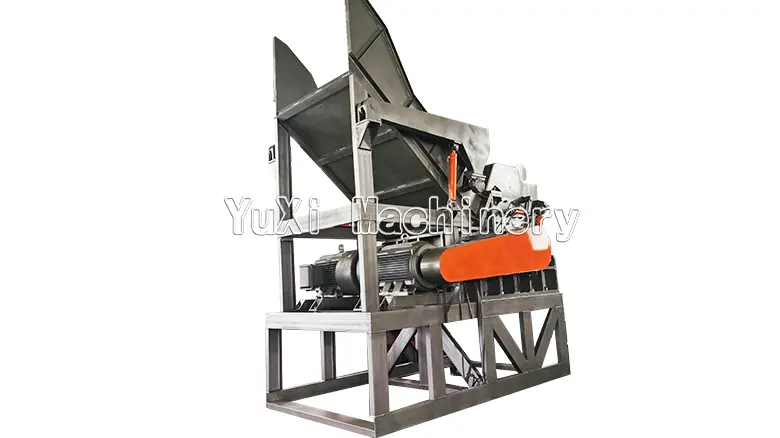
This guide is for industrial hammer mill metal crushers used to reduce and liberate prepared scrap—not feed mills, wood grinders or small laboratory pulverizers.
The maintenance logic follows the machine’s role. In a metal-recycling line, a hammer mill uses repeated high-speed impact together with tearing and shearing. Material leaves through a screen or grate whose opening influences the discharged size. YUXI’s product page also describes a hydraulic system, PLC control and a safety door intended to help remove an unbreakable object from the chamber after the machine is safely stopped. Those features create a different maintenance profile from a low-speed, high-torque double-shaft shredder.
For the mechanical sequence and material path, read the separate hammer mill working principle guide. This article does not repeat that explanation. It focuses on what operators and maintenance teams should inspect, record and escalate.
Why Metal-Recycling Hammer Mill Maintenance Is Different
A hammer mill rotor stores significant rotational energy and repeatedly strikes irregular feed. Even when the feed is nominally “scrap metal,” each load can differ in thickness, density, attached non-metallic material, dirt, loose fasteners and hidden hard objects. The wear pattern therefore changes with the material mix and feeding method.
High-speed balance
Unequal hammer mass, missing hardware or localized buildup can turn normal wear into rotor imbalance. The symptom may first appear as a new vibration trend, bearing heat or pounding sound.
Impact wear
Hammers, pins, liners and screens or grates receive different combinations of impact, abrasion and deformation. A part that still looks “thick enough” may already be cracked or loose.
System effects
Feed surges, blocked discharge, misaligned belts, poor foundation support or a failed downstream conveyor can raise load and vibration even when the rotor parts are not the first cause.
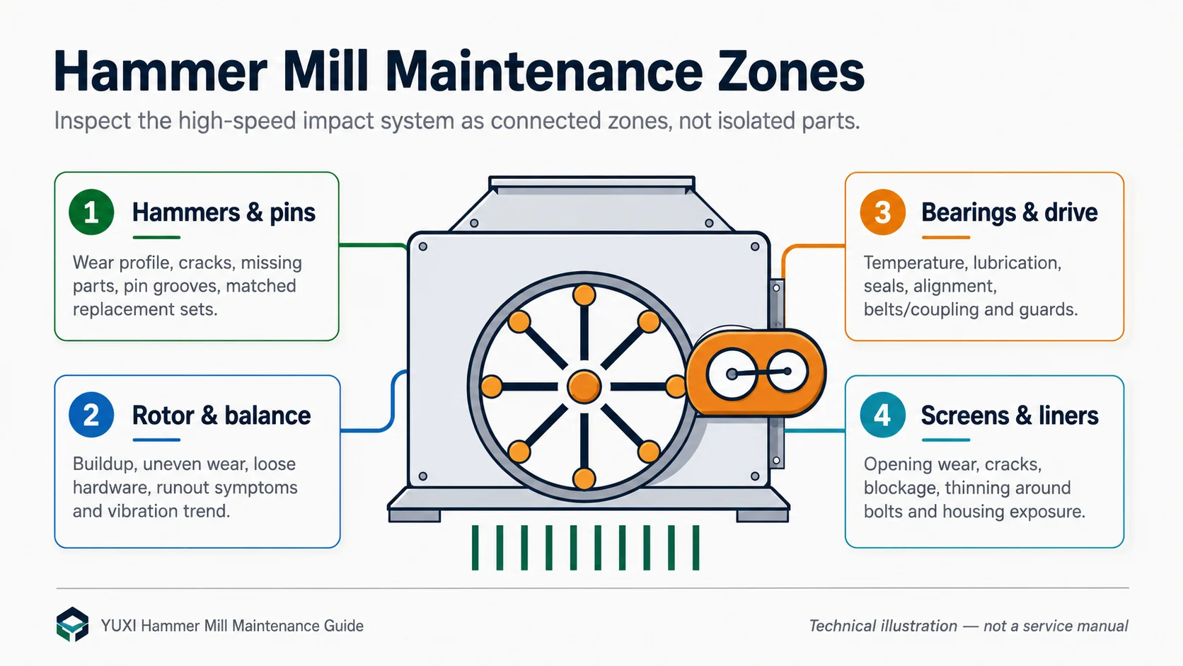
This is why a generic “lubricate and replace worn parts” checklist is not enough. A useful plan must identify how one defect can damage the next component.Uneven hammer wear will increase vibration;continuous vibration will accelerate bearings,fasteners and structural problems;a worn or blocked grate will change the retained material load and output size;blocked discharge will cause mechanical overload in an otherwise healthy mill
Safety Before Inspection, Cleaning or Repair
For U.S. workplaces, OSHA’s hazardous energy control standards apply to services and maintenance that may harm employees by accidentally starting or releasing stored energy sources. The site procedure should identify electrical, mechanical, hydraulic, pneumatic, gravitational and process-related energy, not only the main motor disconnect.
- Stop normal production. Stop feed, allow the chamber to clear where the approved procedure permits, and follow the normal shutdown sequence.
- Identify every energy source. Include the mill motor, feed and discharge conveyors, hydraulic unit, magnets or separators that can move material, stored pressure and rotor inertia.
- Lock and tag. Apply the site’s written procedure through authorized employees and notify affected personnel.
- Release or restrain stored energy. Wait for complete rotor stop, bleed or block hydraulic movement where required, and secure suspended components.
- Verify zero-energy condition. Use the approved test method before opening access points.
- Restore guards before restart. OSHA’s general machine-guarding requirements address rotating parts, nip points, flying chips and sparks.
A hammer mill may also create high noise, flying fragments and sharp scrap edges. NIOSH lists an occupational noise recommended exposure limit of 85 dBA averaged over an eight-hour shift, so hearing risk should be evaluated with site measurements rather than assumptions. See the NIOSH noise-exposure guidance.
OSHA’s metal scrap recycling guidelines also emphasize the hazards surrounding heavy equipment,material handling,noise and contaminated scrap.The maintenance plan should include houseworking,safe access,lighting,personal protective equipment selection,and control of sharp or unstable materials.
Formulate a Layered Preventive-Maintenance Plan
Do not assign the same inspection interval to each component. Use a brief operator check to detect changes, plan inspections to expose wear, and major shutdown work for measurements that require disassembly or alignment tools.
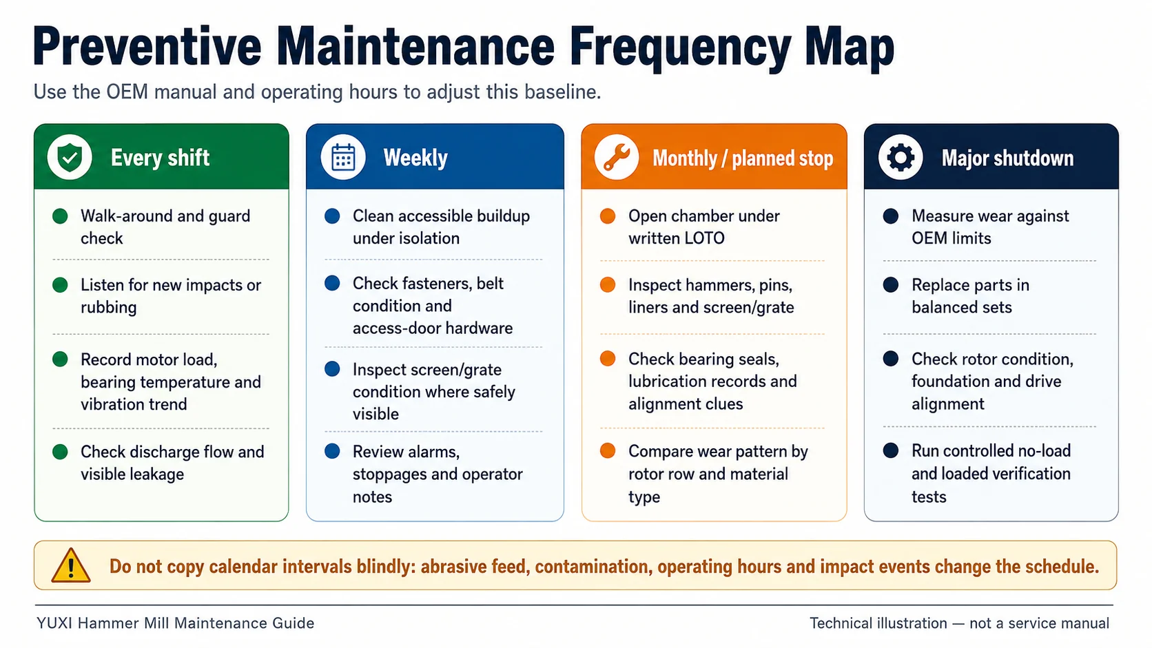
| Frequency layer | Typical tasks | What should change the interval |
|---|---|---|
| Every shift / daily | Guard and access-door check; leak inspection; unusual sound; motor-load trend; bearing temperature; discharge condition; visible fasteners; housekeeping. | New material, recent repair, abnormal impact, higher contamination, startup after extended shutdown. |
| Weekly | Review alarms and stoppages; clean accessible buildup under isolation; inspect belts and external drive condition; verify lubrication records; check structural fasteners where assigned. | Rapid buildup, dusty service, frequent feed surges, weather or ambient-temperature changes. |
| Monthly or planned stop | Internal inspection of hammers, pins, screens or grates, liners, fasteners and chamber; compare wear by row and side; inspect seals and alignment clues. | Abrasive scrap, mixed cast pieces, repeated uncrushable objects, rising vibration or output-size drift. |
| Major shutdown | Measure parts against OEM limits; replace balanced sets; inspect rotor and shaft condition; verify coupling or belt alignment; examine foundation and housing; perform controlled test run. | Operating-hour milestone, wear forecast, production season, repeated defects or supplier recommendation. |
The interval should be expressed in both calendar time and operating hours. Keep a separate trigger for impact events, because one uncrushable object can justify an immediate inspection even when the next planned stop is weeks away.
Daily Pre-Start and Operator Inspection Checklist
The most valuable daily check is a short walk-around performed at the same points, in the same order, with comparison to the machine’s known baseline.
Before startup
- Confirm chamber doors, inspection covers and guards are closed and secured.
- Check the belt or coupling guard, visible belt condition and signs of rubbing.
- Look for loose bolts, fresh metal dust, oil or grease leakage and displaced covers.
- Verify feed and discharge paths are clear and downstream equipment is ready.
- Confirm no tool, part or maintenance lock remains in the machine area.
- Review the previous shift’s alarms, impact events and work orders.
During controlled startup
- Listen for a new rhythmic knock, scrape or belt noise.
- Watch no-load and loaded motor-current behavior against baseline.
- Observe vibration and bearing-temperature trend, not only absolute readings.
- Confirm stable feed, free discharge and normal PLC or hydraulic status.
- Stop and investigate if vibration, sound or temperature changes abruptly.
A new sound or reading matters most when the material and production rate have not changed. Conversely, higher current during a denser or less-prepared batch does not automatically prove a mechanical fault. Record the feed description with the operating data.
Inspecting Hammers and Hammer Pins
The hammer set is the first place many teams look, but visual wear should be interpreted as a pattern. Inspect all rows and both sides of the rotor. A single badly worn hammer may point to feed concentration, a bent or grooved pin, restricted movement, missing hardware or a foreign-object impact.
What to look for on hammers
- Rounded or deformed impact edges that reduce effective striking action.
- Cracks, chips, severe mushrooming or evidence of thermal damage.
- Uneven wear between opposite sides or between rotor rows.
- Restricted swing caused by packed material, deformation or pin damage.
- Missing, incorrectly positioned or unmatched replacement parts.
What to look for on pins, rods and retainers
- Grooves, steps or oval wear where the hammer bears on the pin.
- Bending, cracks, damaged threads or worn retaining features.
- Movement that differs from the opposite rotor position.
- Evidence that a pin is rotating or shifting when it should remain secured.
Schutte Hammermill’s official wear-part inspection guide emphasizes checking hammers, rods, screens, wear plates and bearings, and warns that imbalanced hammer distribution can lead to vibration and reduced efficiency. The exact YUXI arrangement may differ, so do not transfer another manufacturer’s rotation sequence, edge count or replacement procedure.
Rotor Balance, Buildup and Abnormal Vibration
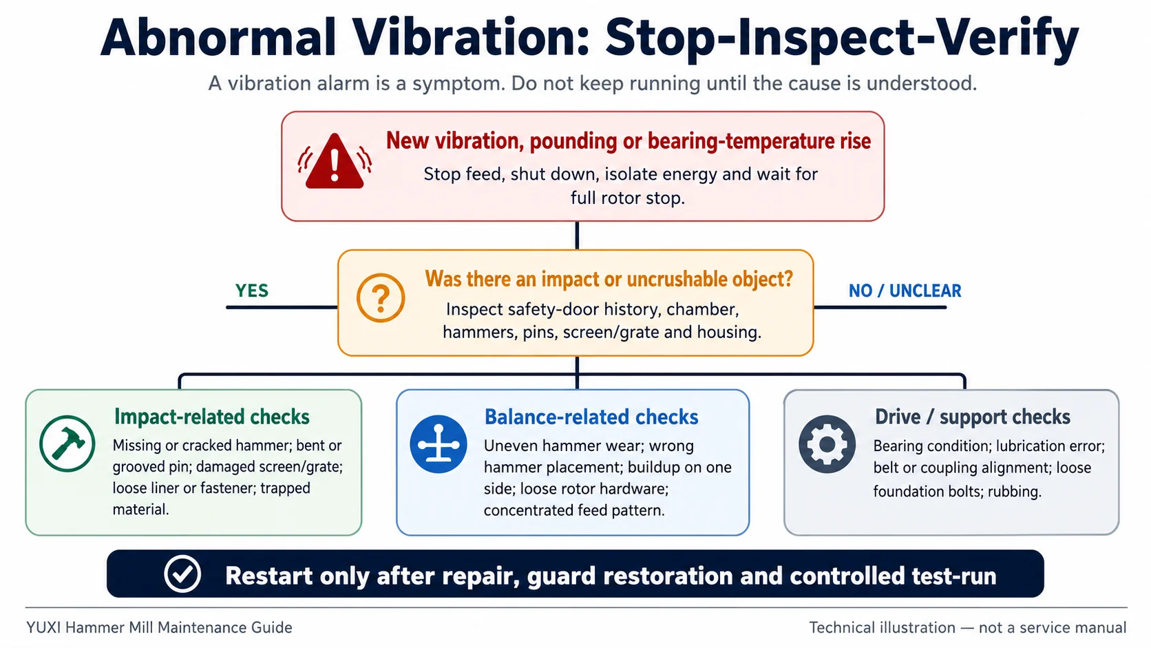
Vibration connects the rotor, bearings, drive, housing and foundation. It can come from uneven hammer wear, material buildup, a loose liner, bearing damage, misalignment, foundation movement or a downstream blockage that changes the retained load.
Stop promptly when the change is sudden
A sudden new vibration, pounding noise or bearing-temperature rise after an impact should be treated differently from a slow trend increase. Stop feed, isolate the machine and inspect for missing or cracked hammers, damaged pins, trapped material, screen or grate damage and loosened internal hardware.
Use trend data for gradual changes
A gradual increase may indicate wear moving toward a limit, recurring buildup, belt or coupling deterioration, or a bearing lubrication and alignment problem. Compare readings at the same locations and similar operating conditions.
After corrective work, verify the machine in stages: assembly and guard check, approved no-load run, comparison of sound/current/temperature/vibration, then gradual loaded operation.
Bearings, Lubrication, Belts and Couplings
Hammer mill bearings operate beside a high-impact rotor. Their condition depends on mounting, alignment, contamination control, lubrication quantity and the loads transmitted by imbalance. Replacing a bearing without correcting the cause can produce a repeat failure.
Track temperature, noise and vibration together
A single temperature reading is less useful than a trend from the same point. Compare left and right bearing locations, ambient conditions, load and lubrication timing. A rise immediately after greasing may indicate too much grease or incorrect distribution; a rise with vibration and new noise may point to damage or alignment problems.
SKF’s official grease-life and relubrication guidance explains that relubrication frequency must prevent grease deterioration from reducing bearing life. Its bearing-damage guidance notes that misalignment adds loads, increases friction and temperature, and shortens service life. Apply these principles using the bearing, speed, load, temperature and grease specified for the machine.
Do not overgrease by habit
“More grease” is not a universal response to heat or noise. Excess grease will lead to whip and temperature increase,while too little or contaminated grease will accelerate wear.Record the type,quantity,point,date,working time and condition before and after re-lubrication.
- Check belts for cracking, glazing, contamination and unequal tension where applicable.
- Look for pulley or coupling misalignment clues, fretting and loose mounting hardware.
- Inspect the guard for secure attachment and evidence of contact.
- Verify motor and mill base fasteners, grout or support condition and visible movement marks.
- Investigate repeated belt failure as an alignment, loading or rotor-condition problem—not only a consumable issue.
Screens, Grates, Liners and Chamber Hardware
The discharge screen or grate influences how long material remains in the chamber and the size range that can leave. YUXI states that the screen opening can be selected according to the required metal particle size. That makes screen or grate condition both a maintenance issue and a process-control issue.
Screen or grate inspection points
- Cracks, tears, bent bars or local opening enlargement.
- Blocked openings and packed material that reduce discharge area.
- Loose mounting hardware or movement marks at supports.
- Uneven wear that matches a concentrated material path.
- Output-size drift or rising motor load with unchanged feed.
Liner and wear-plate inspection points
- Thinning around bolts, edges or high-impact zones.
- Cracks, loose sections or missing fasteners.
- Bright contact marks that indicate movement or rubbing.
- Housing exposure after the protective wear surface has been consumed.
Replacing a liner late can convert a wear-part job into a housing repair. Record location and wear rate, not only the replacement date. If the same zone fails faster every cycle, investigate feed presentation, rotor condition and material mix.
Feed Conditions That Accelerate Wear or Downtime
Maintenance cannot compensate for unsuitable or uncontrolled feed. A hammer mill used as a secondary crusher should receive material within the confirmed feed envelope. Oversized, dense or tangled scrap may require primary size reduction before high-speed impact processing.
| Feed condition | Likely consequence | Operating response |
|---|---|---|
| Large unprepared pieces | Impact shocks, feed instability, chamber damage risk and repeated safety-door events. | Confirm pre-shredding or cutting requirement and maximum feed condition with YUXI. |
| High dirt, sand or abrasive contamination | Accelerated hammer, liner and screen/grate wear. | Improve sorting and cleaning; shorten inspection intervals based on measured wear. |
| Dense cast or hard inclusions | Local impact damage, cracks, pin stress and vibration events. | Separate unsuitable pieces and define an escalation rule after impact. |
| Feed surges | Motor-load spikes, poor liberation, retained material and discharge restriction. | Control conveyor rate and monitor current trend with material description. |
| Blocked downstream equipment | Material backs up, chamber load rises and output appears inconsistent. | Coordinate downstream conveyors and separators; inspect the complete line. |
This distinction stops the team from replacing parts without fixing the process condition that damaged them.
Condition Monitoring: Record the Signals That Change First
A maintenance record becomes useful when it connects machine condition to operating context.
| Indicator | What it may reveal | How to use it |
|---|---|---|
| Motor current or load | Feed density, blockage, worn impact surfaces, retained material, drive friction. | Compare at similar feed rate and material; investigate a sustained change rather than one peak. |
| Bearing temperature | Lubrication, contamination, alignment, load and bearing condition. | Measure at consistent points and note ambient temperature and recent greasing. |
| Vibration | Rotor imbalance, buildup, bearing or drive issues, looseness, support movement. | Trend by location and operating state; set alarms from baseline and supplier guidance. |
| Noise pattern | Loose parts, rubbing, repeated impacts, belt or bearing problems. | Describe sound and timing; do not rely on “sounds bad” alone. |
| Output-size distribution | Screen/grate wear, blockage, hammer wear or feed change. | Sample consistently and link results to the installed opening and material batch. |
| Throughput and stoppages | Loss of impact efficiency, feed problems, downstream restriction or operator response. | Code downtime by root cause rather than one generic “crusher fault.” |
What to Do After an Uncrushable-Object Event
YUXI describes a safety door that allows an unbreakable object to be discharged after the machine is stopped. The door is a damage-control feature, not permission to clear the chamber while energized.
- Stop feed and follow the approved shutdown. Record the time, material batch, alarm and operator observation.
- Apply complete energy isolation. Verify full rotor stop and hydraulic zero-energy condition before access.
- Remove the object with approved tools and lifting methods. Do not place workers under unstable scrap or movable doors.
- Inspect the impact path. Check hammers, pins, screen/grate, liners, fasteners, housing and visible rotor areas.
- Check the external system. Inspect bearing condition, belt or coupling, guards, supports and downstream blockage.
- Perform controlled restart verification. Restore guards, run no-load, compare vibration and current, then load gradually.
A repeated event should trigger a feed-control review: where did the object enter, what upstream control missed it, and should material acceptance, sorting or pre-shredding change?
Spare Parts and Maintenance Records
A spare-parts plan should be based on lead time, wear rate and failure consequence. Keeping every component in stock wastes capital; keeping no matched hammer or pin set can turn a planned repair into a long shutdown.
Typical critical-spares categories
- Matched hammers and approved pin or rod components.
- Screen or grate sections for the installed output configuration.
- High-wear liners, wear plates and specified fasteners.
- Bearing, seal and lubrication items confirmed by model.
- Belt or coupling elements and guard hardware.
- Hydraulic seals or safety-door service items where applicable.
- Sensors, switches and electrical items identified as production-critical.
What the record should capture
- Date, operating hours and processed tonnage where measured.
- Material type, contamination and unusual batch condition.
- Measured wear by component and position.
- Vibration, temperature, motor-load and output trend before and after work.
- Part number, batch or weight-matching information for rotor parts.
- Root cause, corrective action, responsible person and verification result.
Maintenance cost should be evaluated per operating hour and per processed ton, not only by annual spend. The separate hammer mill price guide explains why wear parts, labor, downtime and downstream equipment belong in total-cost planning.
Common Hammer Mill Maintenance Mistakes
Replacing one visible part only
A cracked hammer may be the result of a pin, feed or balance problem. Inspect the full row and opposite positions.
Using calendar intervals without hours
The same “monthly” task represents very different wear exposure in one-shift and continuous-duty plants.
Greasing whenever a bearing feels hot
Heat can come from overgreasing, undergreasing, contamination, misalignment, load or damage.
Ignoring the discharge system
A blocked screen, grate, chute or conveyor can raise chamber load and imitate a mill fault.
Restarting immediately after an impact
A foreign object may have loosened internal parts even when it has been removed successfully.
Copying another manufacturer’s procedure
Hammer arrangement, torque, grease, screen mounting and access sequence vary. Use the YUXI manual.
Maintenance Planning for a YUXI Hammer Mill Metal Crusher
YUXI positions its hammer mill metal crusher for scrap-metal processing in steel plants, foundries, recycling stations, metal-processing facilities, aluminum-product factories and automobile-related applications. The published information describes hammering, tearing and shearing, selectable screen sizing, PLC and hydraulic control, and a safety door for removing an unbreakable object after safe shutdown.
Those features identify the maintenance zones, but they do not provide enough data to prescribe a universal grease interval, hammer wear limit or replacement hour. A project-specific plan should be prepared from the selected machine, material test, operating schedule, feed preparation and downstream line.
Information to confirm before commissioning
- Exact hammer arrangement, identification and matched-set replacement rule.
- Hammer pin or rod inspection and replacement method.
- Installed screen or grate opening and safe removal procedure.
- Bearing model, lubricant specification, quantity and relubrication method.
- Belt or coupling alignment and tension requirements.
- Fastener torque values and thread-locking requirements.
- Normal motor current, bearing temperature and vibration baseline.
- Safety-door isolation, hydraulic pressure release and restart procedure.
- Recommended critical spares and lead times.
- Training responsibilities for operators and authorized maintenance staff.
When comparing service scope, spare parts support and factory tests, please use the questions in the top hammer mill manufacturers guide instead of just comparing the title capacity or motor power.
Prepare a Maintenance Plan Before the Machine Ships
Send your scrap photos or videos,material composition,maximum preparation feed size,estimated operating time,target output,upstream shredder or cutting method,downstream separation process,power supply standard and on-site maintenance resources to the engineering team.These details help define wear parts,access,spares and training requirements more accurately.
Hammer Mill Maintenance FAQ
How often should a metal hammer mill be inspected?
Use every-shift observation, weekly external checks, planned internal inspections and major shutdown measurements. Adjust the interval by operating hours, feed abrasiveness, contamination, impact events and the YUXI manual.
What causes abnormal hammer mill vibration?
Common reasons include uneven hammer wear, wrong hammer placement, missing parts, buildup,damaged pins,loose gaskets,bearing problems,misalignment of belts or couplings,loose support and blockage of discharge.
Should hammers be replaced one at a time?
Not unless the machine-specific procedure allows it and rotor balance is restored. High-speed rotor parts are normally managed as matched positions or sets.
What should be checked after an uncrushable object enters?
After full lockout and zero-energy verification, inspect the object path, hammers, pins, screens or grates, liners, fasteners, housing, bearings, drive, guards and supports before a controlled restart.
Why does bearing temperature rise after greasing?
Possible causes include excess grease, incorrect grease, churning, contamination or an unrelated alignment and load problem. Compare the quantity and method with the machine instructions before adding more lubricant.
How can maintenance cost be reduced?
Control unsuitable feed, trend wear by position, replace parts before secondary damage, keep matched critical spares, coordinate downstream equipment and use operating-hour or tonnage data.