




 Request Quote



Quick Answer: What Is Hammer Mill Rotor Design?
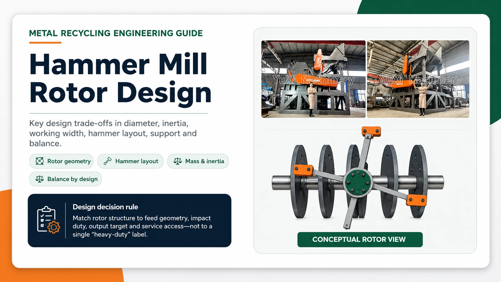
The design of the hammer milling cutter rotor is the engineering of the rotating component,which carries and positions the impact element,and transmits the drive torque,centrifugal load and repeated impact through the shaft,disc,pin,gasket,retainer and bearing.
For metal recycling, the design must do more than rotate hammers. It must deliver useful impact coverage across the working width, tolerate variable and sometimes severe scrap impacts, preserve balance, protect structural components from wear, cooperate with the chamber and discharge system, and allow safe replacement of wear parts.
Rotor Design Is Not the Same as Hammer Mill Working Principle
The Hammer Mill Working Principle guide explains the process sequence: feeding, acceleration, hammer impact, repeated interaction inside the chamber and discharge through a screen or grate. This article deliberately avoids retelling that cycle.
| Working-principle question | Rotor-design question |
|---|---|
| How does the material move and break? | Why is the rotor built with this diameter, mass and hammer pattern? |
| Why does material recirculate? | How do rotor geometry and clearances shape the impact path? |
| How does the screen control discharge? | How should the rotor and discharge restriction be matched structurally? |
| What happens during one operating cycle? | How are loads transmitted and how is balance preserved over the service life? |
The distinction matters for SEO and for engineering. A buyer can understand the crushing cycle and still lack the information needed to compare two rotor proposals.
What the Rotor Must Achieve in Scrap-Metal Service
Metal-recycling feed is rarely uniform. Prepared electric motors, engine parts, cleaned metal containers and pre-shredded mixed scrap differ in density, geometry, ductility, attachment points and single-piece impact severity. YUXI’s product page publicly presents engines, electric motors and metallic drums as example feed categories, which illustrates why the rotor duty cannot be described by one generic material label.
Deliver repeatable impact coverage
The rotating assembly should expose the feed to a useful pattern of impact events across the full working width without creating avoidable dead zones or hammer interference.
Carry combined loads
The shaft, discs, pins and retainers carry rotational forces, drive torque and non-uniform impacts. Local strength is not enough; load paths and cyclic duty matter.
Respond to severe pieces
The design needs a strategy for unusually dense pieces and uncrushable objects, including how impact elements move, how the chamber opens and how the machine is protected.
Preserve serviceability
Wear parts must be replaceable with realistic lifting, access and locking arrangements. A rotor that is difficult to service can create more downtime than its theoretical crushing advantage saves.
Main Parts of a Hammer Mill Rotor Assembly
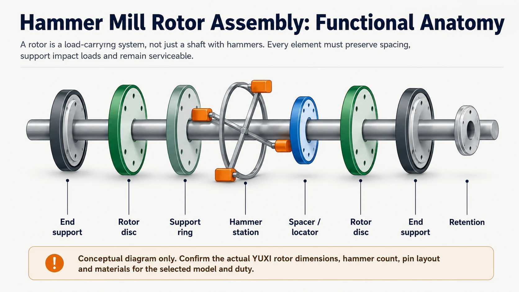
A rotor can be fabricated in several ways, but buyers commonly need to understand the following functions:
- Shaft: carries torque and connects the rotating assembly to the drive and bearing system.
- Rotor discs, plates or bodies: establish hammer stations and transfer pin loads into the shaft structure.
- Hammer pins or rods: support swinging hammers and carry centrifugal and impact-related loads.
- Support rings or intermediate supports: reduce unsupported pin span and add stability where the chosen architecture uses them.
- Spacers, guides or locators: control lateral position and preserve the intended hammer distribution.
- End plates and retention components: keep pins and assemblies in position under rotation and impact.
- Replaceable protection: shields structural parts from direct abrasion and repeated material contact.
One hammer-mill patent describes a segmented rotor using a shaft, multiple discs, shorter hammer pins and support rings to simplify hammer replacement and add pin support. That patent is not evidence of YUXI’s internal construction; it is a useful primary-source example of how service access and structural support can drive rotor architecture.
Swinging Hammers vs Fixed Impact Elements
In a swinging-hammer arrangement, each hammer pivots around a pin. A fixed or semi-rigid impact element maintains a more constrained orientation. These terms are sometimes used loosely in marketing,so buyers should ask for drawings or operation videos instead of relying on labels.
| Design issue | Swinging arrangement | Fixed or constrained arrangement |
|---|---|---|
| Response to a severe impact | The hammer can rotate relative to the rotor, which may reduce some direct shock transfer depending on geometry. | The impact element follows the rotor body more directly, making structural load paths and protection especially important. |
| Impact orientation | Varies with centrifugal position, contact and hammer motion. | More geometrically defined, subject to wear and deflection. |
| Pin and support duty | Pins, bushings and retainers are primary load and wear interfaces. | Mounting body, bolts, welds or integrated supports carry the impact element. |
| Maintenance focus | Hammer, pin, spacer, guide and retention condition. | Element, mounting interface, fasteners and supporting rotor body. |
Research on a hammer crusher with swinging hammers has shown that hammer motion can create fluctuations in rotor angular velocity. The practical lesson is not that swinging hammers are undesirable; it is that rotor dynamics, hammer motion and balance must be evaluated together.
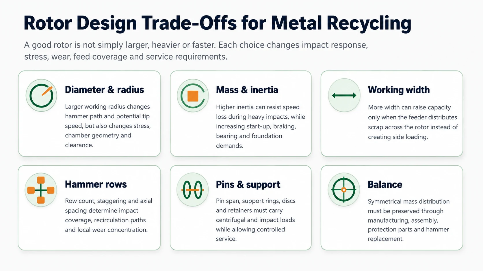
Rotor Diameter and Working Radius
Rotor diameter establishes the physical working radius. Together with the speed and hammer extension, it shapes the path of the hammer and potential peripheral speed. A larger radius can increase the distance from shaft center to impact point, but it can also change the centrifugal load, chamber size, liner geometry, structural stress and maintenance envelope.
The common mistake is to treat RPM as the main design variable. Two rotors running at the same RPM can have different hammer-tip paths and different mechanical demands. Conversely, two rotors designed for a similar peripheral velocity may use different diameters and speeds.
Rotor Mass and Rotational Inertia
Rotational inertia describes the rotor’s resistance to changes in angular speed. It depends not only on total mass but also on where that mass is located relative to the shaft center.
What higher inertia may provide
- Less speed drop during an isolated heavy impact.
- A larger stored-energy buffer between drive torque and sudden material load.
- Potentially more stable response to dense, intermittent scrap when the rest of the system is designed for it.
What higher inertia also demands
- More demanding start-up and stopping control.
- Higher consequences from imbalance or loosened rotating parts.
- Suitable shaft, bearing, frame and foundation design.
- More substantial lifting and service arrangements.
A lighter rotor may accelerate and respond faster, but can experience greater speed fluctuation when feed arrives in dense peaks. Neither direction is automatically superior. The correct choice depends on feed severity, feeder control, drive design and the acceptable speed-recovery behavior.
The related production effect belongs in the Hammer Mill Capacity Guide, which explains continuous throughput and why rotor duty cannot be reduced to a peak tons-per-hour number.
Working Width and Feed Distribution
A wider rotor creates more nominal working area, but the feeder must use that width. Scrap entering one side can produce local hammer wear, asymmetric buildup, uneven chamber loading and underused area elsewhere.
Working width should therefore be evaluated with:
- Hopper opening and material trajectory.
- Chain, belt or vibrating feeder width.
- Expected piece orientation and bridging behavior.
- Distribution devices or controlled feed points.
- Wear inspection across left, center and right zones.
This is an important example of line integration. Rotor geometry cannot correct a feeder that consistently places material in one narrow path.
Hammer Rows, Spacing and Impact Coverage
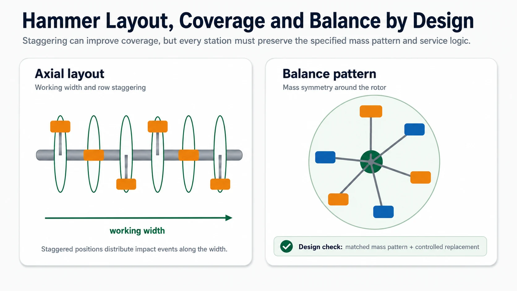
Hammer count alone says little. The design needs to define where the hammers sit axially and circumferentially, how adjacent stations are offset, how much lateral movement is permitted and what clearance exists between moving parts.
Axial spacing
Determines coverage across the working width and interacts with feed distribution, disc spacing and lateral hammer guidance.
Circumferential spacing
Determines the time and angular interval between impact opportunities at each station.
Staggering
Can reduce straight open paths and distribute impact events, but must preserve clearances and service logic.
Mass pattern
Requires the specified hammer and hardware mass to remain symmetrically distributed around the rotor.
The number of hammers should be connected to hammer mass, rotor diameter, speed, desired impact pattern and feed duty. A patent source explicitly links hammer count with grinding type, rotational speed, hammer mass and rotor diameter—useful evidence that hammer count is a system variable rather than an isolated selling point.
Hammer Pins, Rotor Discs and Support Structure
Swinging-hammer rotors place high demands on pins and their supports. The pin experiences hammer weight under rotation, impact transfer, contact and wear at the hammer interface, and bending related to unsupported span.
Questions to resolve include:
| Component | Design question | Why it matters |
|---|---|---|
| Hammer pin | What is the supported span, retention method and replaceable wear interface? | Controls bending, contact wear and service method. |
| Rotor disc or support plate | How are pin loads transferred and how is the disc connected to the shaft or rotor body? | Defines local stress concentration and structural load path. |
| Support ring | Is intermediate support used and how does it affect access? | Can reduce pin span while adding parts and service constraints. |
| Spacer or guide | How is axial position controlled without hammer interference? | Preserves the intended impact coverage and reduces uncontrolled lateral movement. |
| Retention system | What prevents pin or hardware migration under vibration and impact? | Loose rotating hardware can create severe secondary damage. |
Rotor Balance Is a Design Requirement, Not Only a Maintenance Task
Rotor balance begins with geometry, machining, material consistency and assembly pattern. Maintenance can preserve or restore the design condition, but it cannot compensate for a fundamentally poor mass arrangement.
A balanced design considers:
- Symmetry of discs, supports, protection parts and retained hardware.
- Specified hammer arrangement and matched mass groups where required.
- Manufacturing tolerances and runout of rotating features.
- Balance condition before installation and after major repair.
- The effect of asymmetric material buildup or wear.
Research on hammer crushers has connected rotor imbalance with angular-speed variation, vibration, energy behavior and component wear. General rotor-dynamics research likewise treats unbalance as a major excitation source. The practical supplier question is: what balance acceptance method is used, at what assembly condition, and what field condition requires re-verification?
Detailed inspection intervals, vibration troubleshooting and hammer replacement procedures remain in the Hammer Mill Maintenance Guide.
Matching the Rotor to the Chamber, Liners and Screen or Grate
Rotor design cannot be finalized without the stationary parts around it. Hammer path, liner position and discharge restriction determine whether pieces receive useful impacts, circulate unnecessarily or create damaging contact.
| Interface | Design concern |
|---|---|
| Hammer-to-liner path | Enough interaction for the required duty without allowing wear to close the clearance into contact. |
| Hammer-to-screen or grate clearance | Must support output control while accommodating deflection, wear and retained oversize. |
| Feed opening | Should guide material into the intended working zone without exposing the rotor to unsuitable direct impacts. |
| Uncrushable-object route | Needs a defined protection and removal strategy rather than relying on operator improvisation. |
YUXI publicly states that the discharge mesh can be selected according to the required metal-particle size and describes a safety door for removing unbreakable objects. These are relevant system-level features, but the public page does not publish rotor clearances or internal structural dimensions.
Designing for Wear Protection and Service Access
Wear protection should preserve expensive structural components and keep replacement work predictable. Common design questions include whether disc edges, end areas and high-contact zones have replaceable protection, and whether those parts can be changed without disturbing the rotor’s mass pattern.
Serviceability should be reviewed before purchase:
- Can hammer pins be withdrawn within the available workshop space?
- What components must be removed before one hammer station is accessible?
- What lifting points, fixtures and tools are required?
- How are hammers, spacers and retainers controlled during disassembly?
- What balance or runout checks are required after reassembly?
The segmented-rotor patent cited earlier focuses on shorter pins and localized access because conventional long pins can force technicians to remove many hammers before reaching one damaged part. This is a good example of maintenance access shaping rotor architecture.
How the Public YUXI Product Information Relates to Rotor Design
YUXI’s official Hammer Mill Metal Crusher page describes hammering, tearing and shearing actions, selectable discharge mesh, a safety-door concept for unbreakable objects, and PLC plus hydraulic control. The page also shows car engines, electric motors and metallic drums as example materials.
However, the public product page does not disclose a verified rotor diameter, rotor weight, inertia target, shaft size, working width, hammer count, pin span, balance grade, material specification or internal drawing. This article therefore does not invent those values or present a generic rotor as the exact YUXI configuration.
The broader machine definition and application boundary remain in What Is a Hammer Mill Metal Crusher?.
How to Compare Hammer Mill Rotor Designs from Suppliers
| Item | Questions to ask | Evidence to request |
|---|---|---|
| Rotor type | Are the hammers swinging, constrained or fixed? How does the design respond to severe pieces? | Section drawing, operating video and component list. |
| Diameter and speed | What are the working diameter, hammer extension and speed range? | Technical datasheet and design basis. |
| Working width | How is feed distributed across the width? | Hopper and feeder layout plus material-test video. |
| Hammer layout | How many stations, rows and hammers are used, and how are they staggered? | Assembly drawing and replacement pattern. |
| Mass and inertia | What impact duty is the rotor designed to absorb and how is speed recovery evaluated? | Drive/load data or engineering explanation for the stated feed. |
| Pin and support | How are pins supported, retained and replaced? | Maintenance drawing, parts list and service-space requirement. |
| Balance | What manufacturing and assembled balance verification is performed? | Inspection record, acceptance criterion and field recheck procedure. |
| Wear protection | Which structural zones have replaceable protection? | Wear-parts drawing and replacement scope. |
| Uncrushable objects | How are abnormal objects detected, released and removed? | Control narrative, interlock list and operator procedure. |
| Testing | Has the rotor processed representative scrap at the required output condition? | Material description, continuous test log, output sample and load trend. |
Supplier audit and contract questions are expanded in Top Hammer Mill Manufacturers.
Match the Rotor to the Actual Scrap Duty
Send material photos and video, maximum dimensions, single-piece mass, preparation method, capacity target, output requirement and operating schedule. YUXI can then confirm which rotor and complete-line configuration should be quoted.
Safety Boundary for Rotor Inspection and Service
A stopped rotor can retain stored energy, move unexpectedly or expose workers to sharp scrap and heavy suspended parts. Inspection, jam clearing and service require formal energy isolation and guarded access.
- OSHA identifies moving machinery and unexpected startup among scrap-recycling hazards.
- OSHA’s lockout/tagout guidance requires procedures to control hazardous energy during servicing and maintenance.
- Guards, doors and interlocks should not be bypassed to gain production or maintenance access.
- Rotor lifting, support and turning devices must be rated and used under the manufacturer’s procedure.
FAQ: Hammer Mill Rotor Design
What is hammer mill rotor design?
Hammer mill rotor design is the engineering of the rotating assembly, including the shaft, discs or support structure, hammer stations, pins, spacers, retainers, working width, mass distribution and balance concept.
Is a heavier hammer mill rotor always better?
No. More rotational inertia can reduce speed loss during heavy impacts, but it also changes start-up, braking, bearing, shaft, foundation and service requirements. The correct inertia depends on the feed duty and drive system.
What is the difference between swinging and fixed hammers?
Swinging hammers pivot on pins and can move in response to impact, while fixed impact elements maintain a defined orientation. Each arrangement changes shock response, wear pattern, clearances and maintenance needs.
Why are hammer rows staggered?
Staggering can spread impact coverage across the working width and reduce direct open paths. The final pattern must also preserve clearances, avoid interference and maintain the specified mass distribution.
How does rotor width affect performance?
A wider rotor provides more working area only when the feeder distributes material across that width. Poor distribution can create side loading, uneven hammer wear and unused rotor area.
Why is rotor balance a design requirement?
A rotating assembly creates centrifugal force. Uneven hammer mass, missing parts, local buildup or asymmetric protection can increase dynamic forces, vibration and bearing load. The design and service plan must preserve mass symmetry.
What should buyers request from a rotor-design supplier?
Request the rotor type, working diameter and width, hammer count and arrangement, pin-support method, balance standard or acceptance method, replaceable protection, uncrushable-object strategy, service-access plan and representative material-test evidence.
Authoritative References and Use Notes
- ISO 21940-12:2016: Mechanical vibration ? Rotor balancing.
- OSHA 29 CFR 1910.212: General Requirements for All Machines.
- OSHA: Control of Hazardous Energy / Lockout-Tagout.
- OSHA: Guidance for the Identification and Control of Safety and Health Hazards in Metal Scrap Recycling.
- NIOSH: Criteria for a Recommended Standard, Occupational Noise Exposure.