




 Request Quote



A workable refrigerator recycling plant layout is not a row of machines fitted into whatever floor space is left. It is a controlled sequence of receiving, depollution, cabinet preparation, shredding, foam and dust handling, physical separation, product discharge and maintenance access. The right footprint therefore depends on the process boundary, the incoming appliance mix, the required throughput, the building clear height and the utilities that the selected equipment actually needs.
For a new project, freeze the process boundary first. A mechanical line that receives evacuated, pre-treated refrigerator cabinets needs a very different front end from an integrated plant that accepts complete end-of-life appliances. YUXI’s waste refrigerator recycling line separates these two scopes: the mechanical section begins after refrigerant recovery and compressor/oil handling, while an integrated project adds receiving, dismantling and depollution before the shredding section.
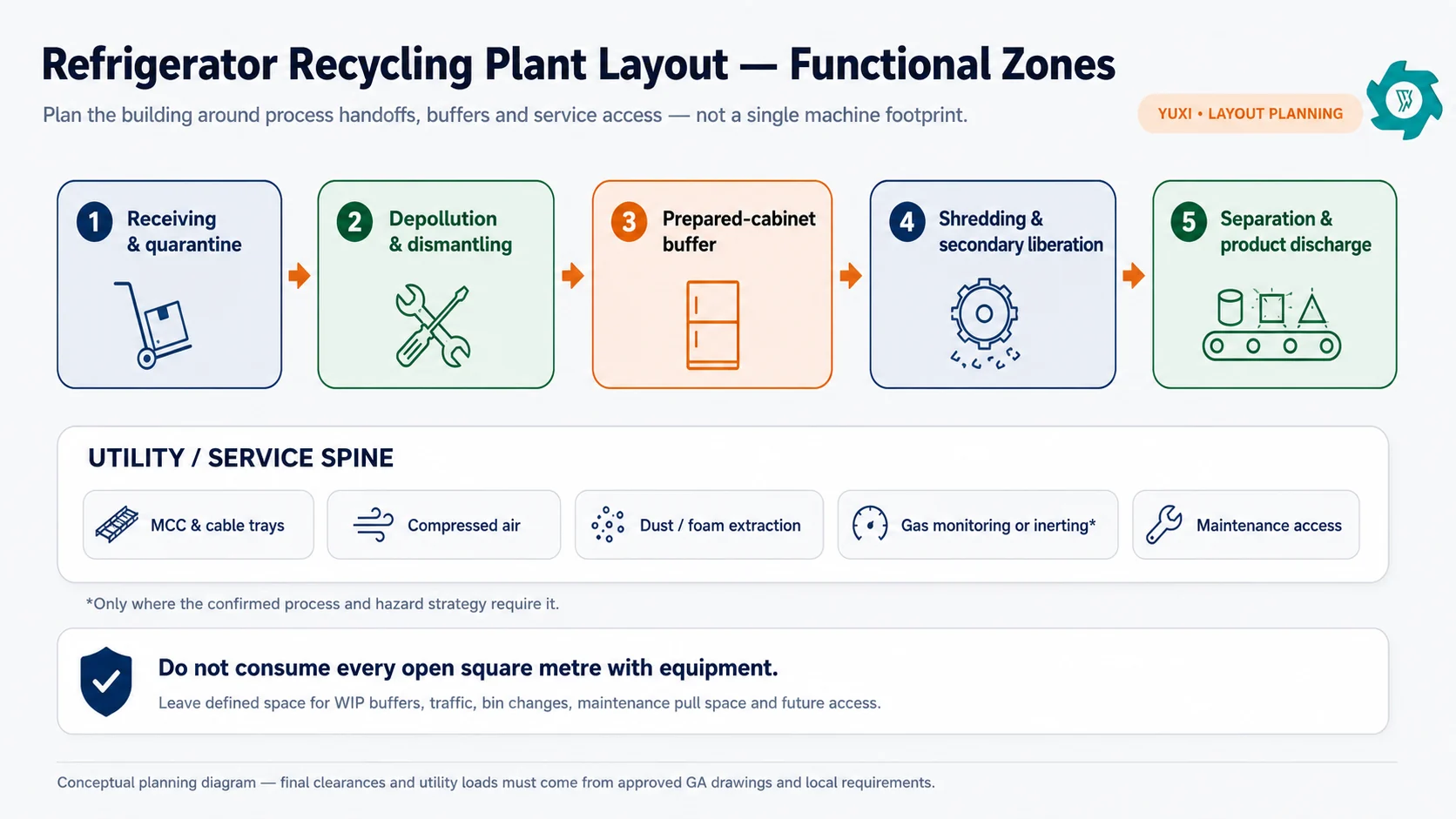
Start With the Process Boundary, Not a Square-Metre Target
There is no responsible universal footprint for a refrigerator recycling plant because two projects with the same headline capacity can include different upstream work, different foam or gas-control strategies, different storage periods and different product-handling methods.
Define what enters the line at the first controlled handoff:
- Complete refrigerators and freezers: the building needs receiving, inspection, refrigerant recovery, compressor and oil handling, removal of unsuitable components, temporary storage for dismantled parts and a release point for prepared cabinets.
- Pre-treated cabinets: the mechanical line can start later, but the layout still needs a feed buffer, primary shredding, secondary liberation, foam and dust collection, ferrous and non-ferrous separation, and product discharge.
- Mixed appliance projects: refrigerators may share some downstream equipment with other white goods, but the incoming routing, depollution boundary and mass balance should not be assumed to be identical.
In the United States, refrigerant-containing appliances have disposal requirements that make the upstream boundary more than an operational preference. EPA guidance states that refrigerant must be properly recovered and also describes responsible appliance disposal as including management of insulating foam, used oil and other components.[1][2] A floor plan should therefore show where an appliance is inspected, where its status is recorded, where recovery work is completed, and where a prepared cabinet is released to the mechanical line.
Divide the Building Into Functional Zones
A practical layout normally becomes clearer when the building is divided into zones with explicit input and output conditions. The exact arrangement can be straight, L-shaped, U-shaped or split across connected halls, but the jobs remain similar.
1. Receiving, inspection and quarantine
This zone absorbs the variability that arrives from collection. It needs enough room to inspect units without blocking unloading, isolate damaged or non-conforming appliances, and separate accepted feed from material whose refrigerant or preparation status is uncertain. If the receiving area is too small, the first queue quickly moves into traffic aisles or the depollution area.
2. Refrigerant recovery and dismantling
The depollution zone should support the sequence of refrigerant handling, compressor removal, oil collection and removal of components that are excluded from cabinet shredding. Workstations need room for the appliance itself, the operator, tools, recovery equipment and containers for removed streams. Storage for compressors, wiring, circuit boards, glass and other dismantled parts should have defined destinations rather than temporary piles beside the line.
3. Prepared-cabinet buffer
A small but controlled buffer between manual pre-treatment and the shredder can decouple two very different types of work. Manual dismantling varies by appliance condition; the mechanical section prefers a steady feed. It should be based on measured variability, shift pattern, the number of upstream stations and how the mechanical line responds to starvation or a downstream stop.
When evaluating throughput, use both units per hour and mass per hour. The relationship changes with refrigerator size and weight, so the refrigerator recycling plant capacity basis should be frozen before the buffer and conveyor duty are finalized.
4. Primary shredding and secondary liberation
The mechanical core usually needs more space than the equipment outline shown on a quotation. Add feed conveyor approach, guarding, platforms, service doors, drive access, removal space for large wear parts and any lifting route needed for maintenance. The same applies to the secondary crusher or liberation stage. A motor that can only be removed after a neighboring conveyor is dismantled is a layout problem, even if the line technically fits on paper.
5. Foam, dust and gas-handling zone
Foam extraction and dust control should be treated as a parallel process, not as accessories added after the machines are positioned. Duct routing, pickup points, fan and collector access, foam collection or compaction, and the handling of any recovered process gas all occupy space and clear height.
EPA RAD guidance describes automated foam-processing approaches that recover blowing agents from insulating foam for reclamation or destruction.[2] Commercial systems may add gas monitoring, recovery or inerting depending on appliance mix and process design. For example, published refrigerator-recycling systems from ANDRITZ/BORSIG and SIC show nitrogen or gas-recovery elements in particular configurations.[3][4] These examples do not mean every plant needs nitrogen.
6. Ferrous, non-ferrous and non-metal separation
Magnetic separation, eddy current separation, air/gravity cleanup and screening work best with controlled feed presentation. Layout should preserve the transfer geometry that the selected separator needs instead of forcing short, steep or crowded conveyors simply to save floor area. Product chutes also need enough fall height and bin-change space to avoid turning clean discharge points into manual rehandling stations.
7. Product and residue storage
Steel, non-ferrous-rich fractions, plastics, PU foam, removed components and residue do not leave the line in the same way. Decide whether each stream discharges to a skip, roll-off container, big bag, bunker, briquetter, baler or downstream process. The discharge method changes both floor area and forklift frequency. Product storage should be sized from dispatch rhythm, not only hourly production.
8. Utility and maintenance spine
Cable trays, compressed-air headers, extraction ducts, control wiring, inspection points and maintenance access become difficult to manage when every utility approaches the equipment from a different direction. A planned utility spine also makes future changes easier because isolation points and branch connections are visible.
Material Flow Should Move Forward, Not Back and Forth
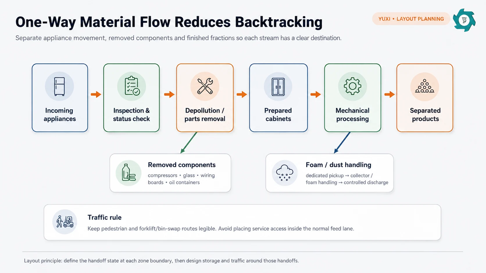
One-way flow is usually easier to operate than a layout that repeatedly crosses itself. An incoming appliance should not pass the mechanical line and then return to a refrigerant-recovery station. Removed compressors should not cross the prepared-cabinet feed lane. Finished steel bins should not require a forklift to enter the operator platform area.
Map at least four kinds of movement separately:
- Main appliance/material flow from receiving to prepared cabinet, shredding, separation and final products.
- Removed-component flow for compressors, oil, glass, wiring, circuit boards and other dismantled fractions.
- Residue, foam and dust flow from pickup points to collection, compaction or controlled off-take.
- People and mobile-equipment flow for operators, forklifts, bin swaps, maintenance carts and emergency access.
A narrow aisle may look acceptable until a full product bin is shown at the discharge point and a maintenance door is opened. The design should be checked in operating states, not only with every guard closed and every bin empty.
Clear Height Can Be as Important as Floor Area
Refrigerator recycling lines frequently use elevated conveyors, platforms, air ducts, cyclones, filters and discharge chutes. A building that is long and wide enough can still be unsuitable if the clear height is too low for the selected transfer arrangement or for safe maintenance above the equipment.
Before approving a building, request general-arrangement drawings that identify:
(1)Highest equipment point and operating platform elevation;
(2)Top of feed hoppers and inclined conveyors;
(3)Duct and extraction connection elevations;
(4)Space above motors, rotors, cutters or screens where lifting may be required;
(5)Clearance below roof trusses, cranes, sprinklers and building services;
(6)Vertical drop required for product chutes, separators and bins.
Do not assume an overhead crane solves every maintenance problem. The hook path, lifting capacity, access between machines and the weight of the heaviest service component all need to match.
Plan Utilities From a Load Schedule, Not a Brochure Number
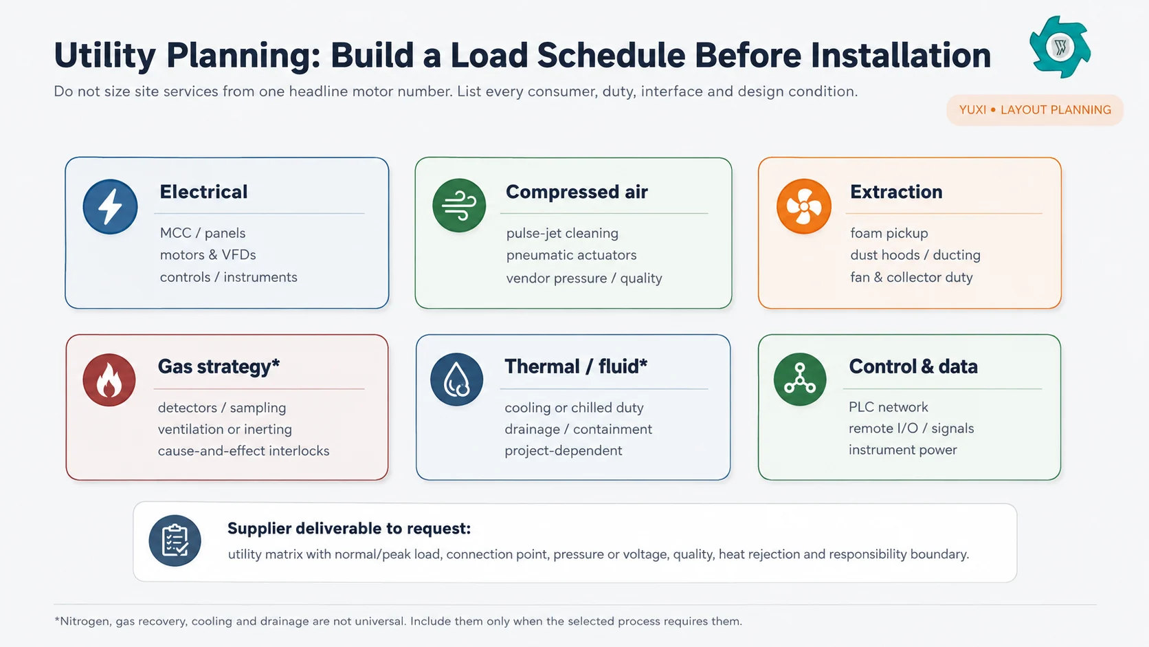
“Installed power” is not a complete utility specification. A refrigerator recycling project can combine large drives with dust-collector fans, pulse cleaning, pneumatic actuators, controls, refrigerant-recovery equipment and project-specific gas or thermal systems. The site designer needs a load list that says what each consumer requires and when it operates.
| Utility / interface | What to confirm | Why it changes layout |
|---|---|---|
| Electrical | Supply voltage/frequency, connected load, normal demand, starting method, MCC boundary, control power | Transformer/MCC location, cable routes, isolation points and heat/load planning |
| Compressed air | Pressure, normal and peak flow, air quality, receiver requirement, consumers | Header routing, drops, service access and compressor-room duty |
| Dust / foam extraction | Pickup points, airflow, static pressure, duct sizes, collector/fan duty, discharge method | Duct routing, collector location, clear height and maintenance space |
| Gas monitoring / ventilation / inerting | Only if required by the process design: gases, detector locations, ventilation or inerting concept, interlocks | Sensor access, duct/piping routes, gas supply or generator space and controlled-area interfaces |
| Cooling / chilled service | Only if included equipment requires it: supply/return temperatures, duty and heat rejection | Skid space, piping, outdoor equipment and drainage considerations |
| Oil / liquid containment | Collection containers, transfer method, spill-control boundary and housekeeping method | Changes depollution workstation layout and local floor/containment details |
| Controls & data | PLC architecture, remote I/O, network, instrumentation, interface to site systems | Panel locations, cable separation and commissioning access |
Electrical power
Ask for both connected load and expected operating demand. Large shredders and crushers are only part of the total. Fans, pumps, conveyors, separators, air compressors, heaters or coolers, and auxiliary systems can materially change the site load. The supplier should identify the electrical responsibility boundary: machine-mounted equipment, local panels, MCCs, transformers, field cabling and site distribution are not automatically included in the same scope.
Compressed air
Pulse-jet dust collectors and pneumatic devices may require compressed air. The line supplier should state the required pressure, peak flow and air quality. Peak demand matters because a collector cleaning cycle and several actuators can overlap.
Dust and foam extraction
The duct system must connect pickup points to the fan/collector while preserving access for inspection and cleaning. Short ducts can reduce pressure loss, but collector placement also depends on fire strategy, structural support, weather exposure, material discharge, local code and maintenance access.
Gas handling, ventilation and nitrogen
Some refrigerator-recycling systems use nitrogen inerting; others use different combinations of enclosure, negative pressure, gas monitoring, ventilation or recovery. Published ANDRITZ/BORSIG work, for example, uses nitrogen in a process-gas recovery concept, while an SIC plant description includes a nitrogen self-generation system and pentane/oxygen detection.[3][4] The correct utility list comes from the confirmed appliance mix, process enclosure and hazard assessment.
Because flammable refrigerants or blowing agents may affect the safety concept, layout, instrumentation and shutdown logic should be coordinated. The broader engineering questions are covered in the refrigerator recycling plant safety guide.
Maintenance Access Is Not Spare Space
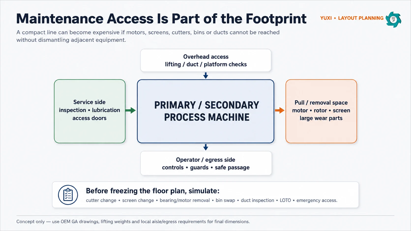
Every machine has an operating envelope and a maintenance envelope. Before the floor plan is frozen, simulate the jobs that will eventually require the most space:
(1)Shredder cutter, spacer or bearing work;
(2)Crusher rotor, hammer, liner or screen replacement where applicable;
(3)Motor and gearbox removal;
(4)Separator belt or rotor service;
(5)Duct inspection and collector maintenance;
(6)Bin, big-bag or container replacement;
(7)Access for mobile lifting equipment;
(8)Lockout/tagout and verification at energy-isolation points.
OSHA’s lockout/tagout standard addresses servicing and maintenance where unexpected energization or release of stored energy can injure workers.[5] The layout does not replace an energy-control program, but it can either support or obstruct it. Isolation points that are hidden behind conveyors, blocked disconnects and maintenance doors that open into traffic all make safe servicing harder.
Walking and working surfaces also need safe access and egress and must support their intended loads.[6] That matters for elevated platforms, stairs, service decks and areas where loaded bins or lifting equipment operate. Final aisle widths, egress routes, platform details and structural loads should be checked against the applicable local requirements rather than copied from a generic layout drawing.
Three Common Layout Patterns
Straight-through layout
Best when: the building is long enough and receiving and dispatch can sit at opposite ends or along a clear logistics route.
Advantages: easy-to-understand material direction, fewer crossing points and simple future extension at one end.
Watch for: long cable/duct runs and excessive building length if all utilities are placed at one end.
L-shaped or U-shaped layout
Best when: an existing building has limited length or the project needs receiving and dispatch on the same side.
Advantages: can shorten some logistics routes and fit around columns or existing rooms.
Watch for: transfer corners, crowded forklift movements and the temptation to place maintenance access inside the return leg.
Split-zone layout
Best when: depollution and mechanical processing need different rooms, environmental controls or working conditions.
Advantages: makes the supply boundary and housekeeping zones clear.
Watch for: the handoff conveyor or transport method between zones, fire/door interfaces, buffer ownership and communication between operators.
How to Estimate Required Space Without Inventing a Fixed Footprint
A useful early-stage estimate is built from the approved equipment arrangement, not from a generic “m² per tonne” rule.
Required building area = equipment footprints + operating clearances + maintenance pull space + WIP buffers + product storage + traffic/egress + utilities + environmental systems + expansion allowance.
Then test the plan at three operating moments:
- Normal production: all expected buffers and product containers are partly occupied.
- Downstream stop: identify where material accumulates safely without blocking upstream depollution or emergency access.
- Major maintenance: show guards open, the largest component removed and lifting equipment in position.
This approach usually exposes space that was absent from a machine-only proposal. It also gives the supplier a concrete basis for revising conveyor lengths, discharge elevations and platform locations.
What to Put in the Layout RFQ
A supplier can only produce a meaningful layout if the site and feed information are specific. Send:
(1)Building internal length, width and clear height.
(2)Column grid, wall openings, doors, loading docks, pits and fixed obstructions.
(3)Available floor-loading information and any prohibited foundation areas.
(4)Incoming refrigerator/freezer dimensions, weight range and typical mix.
(5)Exact feed condition at the mechanical-line inlet.
(6)Required sustained units/hour and tonnes/hour.
(7)Expected upstream and downstream operating hours per shift.
(8)Required product streams and how each product will be stored or removed.
(9)Electrical supply and available site utilities.
(10)Known local environmental, fire, electrical and worker-safety requirements.
(11)Preferred receiving and dispatch doors plus forklift routes.
(12)Any future capacity or product-expansion requirement.
Ask the supplier to return a general-arrangement drawing with machine outlines, platforms, major service clearances, material-flow arrows, utility connection points, duct routes, maintenance pull zones and a utility load schedule.
Layout Mistakes That Commonly Appear Late
No buffer between manual and mechanical work
The shredder alternates between starvation and surges because dismantling variability was never absorbed.
Product bins block service doors
Discharge works during commissioning, but routine bin changes occupy the only maintenance route.
Ducts are added after equipment placement
Extraction routes become long, crowded or inaccessible because no ceiling/side corridor was reserved.
Only floor area is checked
Elevated conveyors or filters conflict with roof steel, cranes, sprinklers or existing building services.
Installed power is treated as the full utility schedule
Compressed air, extraction fans, controls and project-specific gas or cooling systems appear after site services are sized.
No maintenance-state review
The line fits with every machine closed, but the largest component cannot be removed without dismantling adjacent equipment.
Final Layout Review Before Installation
Before civil work and installation begin, review the drawing with operations, maintenance, electrical, EHS/fire stakeholders and the equipment supplier. Walk through the process as if the plant were already running. Where does an uncertain appliance wait? Where does a removed compressor go? What happens if the crusher stops while depollution continues? Which isolation point is used before a shredder inspection? How is a full steel bin replaced? How will the dust collector be reached?
The final drawing should answer those questions without relying on temporary workarounds.
Plan Your Refrigerator Recycling Plant Around the Real Site
Send YUXI your workshop dimensions, column grid, clear height, appliance photos, pre-treatment condition, target capacity, required output fractions and available utilities. The project team can use those inputs to develop a refrigerator recycling line arrangement and equipment configuration for the actual building rather than forcing a generic footprint into the site.
FAQ
How much space does a refrigerator recycling plant need?
Required space depends on whether the plant receives complete appliances or pre-treated cabinets, the selected capacity, the number of dismantling stations, mechanical equipment, foam/dust/gas systems, product storage, traffic routes and maintenance access. Start with the equipment GA drawings and add the operating and maintenance envelopes.
What workshop information should I send before a layout is designed?
Send internal length, width and clear height, the column grid, doors and loading points, fixed obstructions, available floor-loading information, electrical supply, site utilities and the preferred receiving/dispatch routes. Also send the appliance size and weight range and the exact pre-treatment condition.
Does every refrigerator recycling line need nitrogen?
No. The correct design depends on the appliance mix, expected blowing agents or refrigerants, enclosure, ventilation/recovery concept, gas monitoring and applicable local requirements.
Where should the dust collector be located?
The collector position should be coordinated with duct pressure loss, fire and explosion protection strategy, structural support, maintenance access, weather exposure, collected-material discharge and local requirements. It should not be positioned only by choosing the shortest possible duct route.
Why is a buffer needed before the shredder?
Manual depollution and dismantling do not run at perfectly constant speed. A controlled prepared-cabinet buffer can reduce starvation and isolate short upstream variations from the mechanical line. Its size should be based on actual workload variation and the operating strategy, not an arbitrary number of refrigerators.
Can an existing building be used for a refrigerator recycling line?
Often yes, but check more than floor area. Clear height, columns, floor loading, doors, traffic routes, foundations, utility capacity, duct routing, maintenance lifting, fire/egress conditions and product logistics can all determine whether the building is suitable or whether the line needs a different arrangement.
References
- U.S. EPA — appliance disposal.
- U.S. EPA RAD — appliance recycling guidance.
- Waste Management World — refrigerator recycling plant context.
- SIC Plant — refrigerator plant layout description.
- OSHA 1910.147 — lockout/tagout.
- OSHA 1910.22 — walking-working surfaces.