




 Request Quote



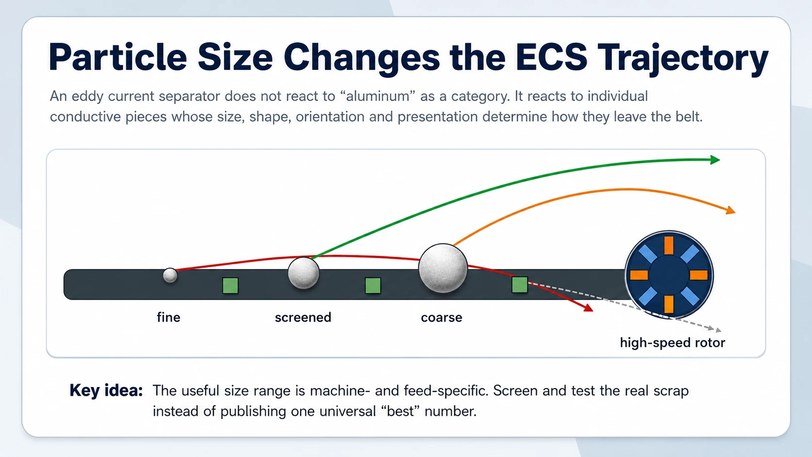
A separator demonstration often begins with the easiest material in the sample: clean, dry aluminum pieces large enough to see from across the workshop. They leave the belt with a convincing jump. Then the production fraction arrives. It includes flakes, curled profile pieces, small cast fragments, plastic, dirt and a much wider size distribution. The clean arc disappears, aluminum starts showing up in the residue, and the splitter is moved back and forth without a stable answer.
That is not evidence that eddy current separation “does not work.” It is usually evidence that particle size was treated as one catalog line instead of a process variable. The machine acts on individual conductive particles. Their dimensions change how eddy currents form, how strongly the particle is accelerated, how it rotates or rolls, and whether its flight path stays separate from the non-metal stream.
Why Particle Size Changes Eddy Current Separation
An eddy current separator uses a rapidly changing magnetic field at the discharge end of a conveyor. A conductive non-ferrous particle passing through that field develops induced currents. Those currents create a magnetic response that changes the way the particle leaves the belt. The non-metal background receives no equivalent electromagnetic push, so it normally follows a shorter ballistic path.
This description is useful, but it hides the practical question: how much useful motion does the aluminum piece gain before gravity, belt velocity, rolling, drag and contact with other pieces determine the landing point?
The size effect is not simply “bigger metal means stronger separation.” The relevant result is the particle’s acceleration and trajectory, not force alone. A larger particle can support a larger induced-current loop, yet it also has more mass. At some point the magnetic field may act unevenly across the piece, especially when part of a large or irregular object sits farther from the rotor. The landing zone can widen even while the absolute force remains high.
A controlled study by Cao and co-authors combined simulation and physical experiments and concluded that an optimum particle size exists for a specific separator condition. The same paper explains why fine-particle separation can be improved by changing factors such as rotational speed and pole arrangement. That wording matters. It supports process-specific testing, not a universal millimeter range. The laboratory experiments used controlled spherical aluminum and brass particles, so an industrial plant should not transfer the exact test dimensions to folded sheet, wires or mixed shredder scrap without validation.
Why We Do Not Publish One “Best” Aluminum Particle Size
Search results and equipment quotations often present a single minimum and maximum size. That can be useful as a machine screening question, but it is not a process guarantee. Two separators with the same belt width can use different rotor diameters, pole counts, pole pitch, magnetic arrangements and operating speeds. The same nominal aluminum piece can therefore see a different field gradient and leave the belt at a different angle.
The feed changes the answer again. A 20 mm square of flat sheet, a 20 mm ball-like casting fragment and a 20 mm length of wire are all “20 mm” in a simple report. Their projected area, contact with the belt, rolling behavior and aerodynamic drag are not the same. Moisture and dust add adhesion. A deep burden causes shielding and collisions. Composite pieces remain partly non-metal and partly aluminum until liberation opens them.
Research on real scrap trajectories has identified size, conductivity and initial orientation as primary particle parameters, while also showing that particle-particle interaction affects grade and recovery. In plant language: a size range that works when pieces are hand-spaced may fail when the same material is fed as a crowded layer.
Our practical rule is to begin with the coarsest fraction that provides enough liberation, then narrow the size distribution only as far as the product and separator test justify. Grinding finer than necessary increases fines, dust, wear and the amount of material that may need another recovery method. Oversize that is still composite may need more liberation; oversize that is already clean aluminum may be better diverted around the ECS.
What Happens When the Aluminum Fraction Is Too Fine
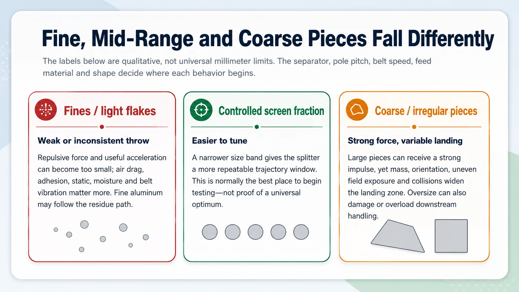
Fine aluminum is the first place a visually impressive separator can disappoint. The particle is conductive, but the useful electromagnetic force and acceleration can fall rapidly as size decreases. Gravity is still present. So are aerodynamic drag, belt vibration, static effects and adhesion to damp plastic or dust. The result is often a short, unstable trajectory that overlaps the residue stream.
Fine pieces also suffer from presentation problems. A thin aluminum flake can sit under a larger plastic chip and never receive a clean exposure to the field. It may stick to a wet belt, cling to another particle or leave the belt at an orientation that increases drag. A deep feed bed makes all of these effects worse.
The wrong response is to increase rotor speed, belt speed or splitter distance blindly. A faster rotor may improve the response of a tested fine fraction, but it can also change scatter, wear, heating and the behavior of larger pieces. Moving the splitter to capture more fines may pull more non-metal into the aluminum product. The change must be judged by both recovery and product quality.
Better questions for a fine-fraction problem
How much aluminum is actually in the fines? Is it liberated metal, foil, wire, composite dust or coating? Is the fraction dry and free-flowing? Can the feed be screened more tightly? Does the available separator have a rotor and pole arrangement intended for this fraction? Is another recovery stage more appropriate than forcing the same ECS to handle both fines and coarse scrap?
Those questions protect the project from an expensive mistake: optimizing the machine for a fraction that contains little recoverable value while reducing performance on the main product stream.
Why Coarse Aluminum Pieces Are Not Automatically Easy
Coarse aluminum often produces a long visible throw, but “long” is not the same as “repeatable.” A heavy cast fragment may roll at the end of the belt. A bent profile section can tumble. Thin sheet can flutter. A hollow or folded object may trap non-metal and change direction after a collision. When landing points spread, the splitter has to choose between aluminum loss and residue carryover.
The controlled particle-size study cited above describes another limit: as size increases, part of a particle may extend beyond the most effective magnetic-field region. Eddy-current distribution becomes less uniform, and the landing-point distribution can widen. This does not mean every large particle fails. It means the separator’s magnetic geometry must be considered relative to the particle dimensions.
Oversize can also be a process signal. If coarse pieces are still aluminum-plastic composites, more liberation may be necessary. If they are already clean and saleable, sending them through a high-speed separator may add no value. A bypass or pre-pick can protect capacity and reduce unnecessary collisions at the ECS discharge.
How Screening Improves Aluminum Eddy Current Separation
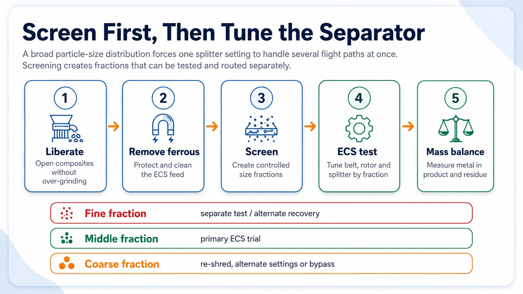
Screening does more than remove fines. It converts an undefined mixed feed into fractions that can be tested, tuned and routed deliberately. This is often the decisive step between a separator that works in a demonstration and a separator that performs continuously.
Imagine one feed containing 3 mm flakes, 20 mm profile fragments and 80 mm cast pieces. One belt speed and one splitter position must separate all three from plastic and rubber. The fine metal may not travel far enough. The middle fraction may separate cleanly. The coarse pieces may scatter. The operator can only compromise.
After screening, each fraction can have its own answer. The fine stream may need drying, a dedicated fine-particle separator or an alternate recovery route. The middle fraction may be the main ECS feed. The coarse stream may be re-shredded, manually checked, treated with different settings or bypassed when it is already clean.
Screen cuts should therefore come from the measured particle-size distribution and separation test, not from a copied flow sheet. Collect a representative sample, perform a sieve or screen analysis that reflects the real material, then test the fractions separately. Choose cut points where trajectory overlap, product contamination or aluminum loss changes meaningfully.
Particle Size Cannot Be Separated from Shape and Orientation
A particle-size report normally uses a screen opening or one measured dimension. The ECS sees the complete object at the instant it reaches the rotor. That is why shape and orientation deserve their own notes in the factory test.
| Particle form | What can happen at the ECS | What to record |
|---|---|---|
| Flat sheet or foil flake | Large projected area and drag; may flutter, overlap or stick when damp. | Thickness, flatness, moisture and whether flakes arrive as a single layer. |
| Compact casting fragment | Higher mass and rolling tendency; may show a strong but broader landing zone. | Maximum dimension, thickness, roundness and impact damage. |
| Wire or narrow strip | Orientation can change suddenly; long pieces can tangle or bridge. | Length distribution, curl, bundles and any screen blinding. |
| Folded profile fragment | May trap rubber, plastic or steel and behave as one composite object. | Liberation, attached material and whether another size-reduction pass changes the result. |
| Hollow or layered piece | Apparent size may be large while effective conductive mass and stability are low. | Wall thickness, trapped material and landing-point scatter. |
This is one reason we prefer photographs of every screen fraction, not only the sieve analysis. Two samples can share the same cumulative size curve and still behave differently because one is made of compact fragments while the other is dominated by thin flakes.
Burden Depth: The Particle Must Reach the Field as an Individual Piece
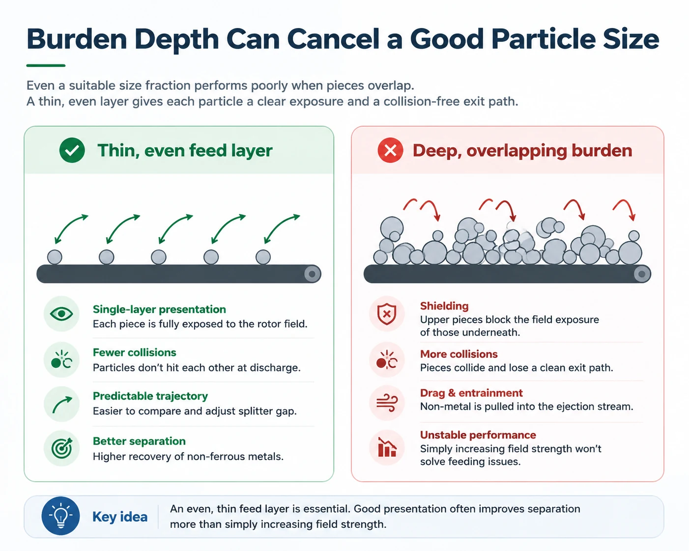
A suitable particle size can still fail when the feeder delivers a deep or pulsing bed. Pieces on top shadow pieces below. Metal and non-metal collide at the discharge point. Aluminum can push plastic across the splitter, while a light metal flake trapped underneath follows the short residue path.
In our experience, hand-spread trials often look better than continuous production for exactly this reason. A technician places material in a near-monolayer for the video. The installed line later receives surges from a conveyor, and the separation window collapses.
The feeder and conveyor are therefore part of the separation machine. The practical target is a thin, even layer across the useful belt width, not simply an average tons-per-hour number. Watch the feed for peaks, bare belt zones, rolling clusters and material accumulating at the sidewalls. Record burden depth during the test so a clean result can be reproduced after installation.
Why Magnetic Removal Still Comes Before the Particle-Size Discussion
Particle-size optimization is wasted if accessible steel is still entering the high-speed ECS area. Ferrous pieces can contaminate the eject product, collect around the rotor zone, disturb flight paths and increase the risk of belt or shell damage. The upstream magnet should remove iron and carbon steel after enough liberation has taken place.
The related YUXI guide on magnetic separator vs eddy current separator for aluminum scrap covers that equipment boundary in detail. This article stays narrower: once the ECS has the correct non-ferrous-versus-non-metal job, particle-size distribution and presentation determine whether it can perform that job consistently.
Do not confuse magnetic removal with perfect liberation. A steel screw locked inside a folded aluminum piece remains part of the composite until shredding or impact opens the interface. Likewise, an aluminum-plastic laminate cannot be separated by flight path while it is still one object.
Where Particle-Size Control Fits in a YUXI Aluminum Recycling Line
YUXI’s public scrap aluminum recycling line does not force profiles, sheets, mixed scrap and chips through one fixed arrangement. For mixed aluminum and profile-related projects, the published route can include primary shredding, optional secondary crushing, magnetic removal, screening and an optional ECS. The page also states that feed size, contamination, required output and workshop conditions are part of the engineering basis.
That route is important for this topic because each stage changes the ECS feed. A shredder makes long or bulky scrap conveyable. A hammer mill or crusher is added only when more liberation or size refinement is justified. The magnet removes exposed ferrous material. The screen creates particle-size fractions. The YUXI eddy current separator then separates conductive non-ferrous pieces from a suitable non-metal stream by changing their discharge trajectory.
The sequence is not permission to over-process every aluminum feed. Clean fabrication offcuts may need volume reduction and ferrous control but little non-metal separation. Chips and turnings have liquid, fines and density problems that point toward drainage and briquetting rather than a conventional mixed-scrap ECS route. The aluminum shredder vs hammer mill guide explains how to decide whether primary shredding, impact refinement, both stages or neither are justified before final separation.
A Practical Test for Eddy Current Separator Particle Size
The most useful factory test does not ask, “Can the machine throw aluminum?” It asks, “Where did the aluminum in each size fraction go under a realistic continuous feed?”
- Build a representative sample. Include ordinary material, not a hand-picked batch of clean pieces. Record source, total weight, moisture, visible steel and non-metal content, and the preparation already completed.
- Measure the particle-size distribution. Use screens that reflect the real feed and likely process choices. Photograph each fraction and note dominant shapes, not only weight percentages.
- Remove accessible ferrous material. Record steel in the product and aluminum carried into the ferrous reject. A magnetic stage that steals aluminum can make the ECS look better than the whole line actually is.
- Run each fraction separately. Record feeder setting, burden depth, belt speed, rotor configuration or speed where adjustable, splitter position, runtime, stops and any recirculation.
- Weigh every output. For each size fraction: feed = recovered non-ferrous product + non-metal residue + fines + oversize/recirculation + retained material. Investigate the difference instead of hiding it.
- Sample both sides of the splitter. Measure aluminum in the residue and non-metal in the eject. A long aluminum throw is not enough if product contamination rises at the same time.
- Repeat at realistic loading. Re-run the most promising fractions with continuous feed. A result obtained from a thin hand-fed trickle is not a production acceptance test.
- Choose screen cuts and settings together. The best configuration is the one that meets the agreed product and recovery targets at stable throughput with acceptable recirculation and cleaning.
For a project review, send the particle-size analysis, fraction photographs, material composition, target throughput and required output together. A request that only says “aluminum scrap, 5 t/h” leaves the separator supplier guessing at the most important variables.
Troubleshooting Aluminum Loss by Symptom
| Observed symptom | Likely causes to check first | Test before changing hardware |
|---|---|---|
| Fine aluminum follows residue | Fraction too fine for current setup, damp or dusty feed, deep burden, weak exposure, splitter too far. | Dry and screen the fraction; reduce burden depth; test settings on fines alone; quantify the value actually present. |
| Clean aluminum product contains too much plastic | Splitter moved to chase recovery, deep feed, collisions, broad size distribution, flat plastic pieces sharing a long trajectory. | Narrow the size band; reduce loading; inspect discharge video frame by frame; measure grade and recovery together. |
| Coarse aluminum lands across a wide zone | Irregular shapes, rolling, oversize relative to rotor field, excessive belt speed or collisions. | Test coarse fraction separately; pre-pick clean pieces; resize only composites; compare a bypass route. |
| Good hand-fed result, poor continuous result | Surging feeder, uneven belt loading, sidewall accumulation, changing moisture or composition. | Record burden-depth profile and feed rate over time; stabilize the feeder before retuning the ECS. |
| Steel appears in ECS product | Incomplete magnetic removal, hidden inserts, deep burden at the magnet, weak liberation. | Audit the magnetic reject and product by size fraction; improve liberation or magnet presentation first. |
| Results change after screen wear | Particle-size distribution drift, broken screen media, blinding or changed recirculation. | Repeat sieve analysis and compare with the acceptance sample before changing separator settings. |
Send the Size Distribution, Not Just the Material Name
A useful YUXI separation review starts with representative photos or video, maximum dimensions, screen fractions, dominant particle shapes, moisture, steel and non-metal content, intended throughput, required product and workshop constraints. That information allows the shredder, screen, magnet, feeder and ECS to be considered as one process rather than five isolated machines.
Frequently Asked Questions
What is the best particle size for eddy current separation of aluminum?
There is no responsible universal number. The useful range depends on rotor geometry and speed, pole pitch, belt speed, particle shape, conductivity-to-density behavior, liberation, moisture, burden depth and the product specification. Screen a representative sample into practical fractions and test each fraction under recorded settings.
Why do fine aluminum particles report to the residue stream?
As particle size falls, the useful electromagnetic impulse and acceleration can become too small relative to gravity, air drag, adhesion, static effects and belt motion. Fine pieces are also easier to hide under larger particles. Drying, screening, a thinner feed layer and a separator configured for the fine fraction may help, but the test must confirm the result.
Are larger aluminum pieces always easier to eject?
No. A large piece may receive a strong force, but its mass, irregular orientation and uneven exposure to the magnetic field can widen the landing zone. Large flat pieces may flutter; cast chunks may roll; oversize can collide with neighboring pieces or exceed the intended machine range.
Why should aluminum scrap be screened before an eddy current separator?
Screening narrows the particle-size distribution, reduces trajectory overlap and allows the feeder, belt speed, rotor setting and splitter position to be tuned for one fraction. It also creates clear routes for fines, oversize and recirculation instead of forcing one separator setting to compromise across the whole feed.
Does shape matter as much as particle size?
Size and shape interact. A thin flake, wire, folded profile fragment and compact casting can have similar nominal dimensions yet behave differently because orientation, aerodynamic drag, rolling and contact with the belt change the flight path. Use real scrap in the test rather than machined reference pieces alone.
Should magnetic separation come before the eddy current separator?
Accessible iron and carbon steel are normally removed first. This reduces ferrous contamination, protects the high-speed ECS area and gives the operator a cleaner feed to tune. The magnet still needs adequate liberation and an even layer; it cannot remove steel that remains locked inside a composite piece.
How should an ECS particle-size test be documented?
Record the source and weight of the feed, sieve or screen fractions, moisture, visible composition, burden depth, feed rate, belt speed, rotor configuration, splitter position, runtime, stops and the weight and composition of every output. Repeat at a realistic continuous rate and calculate a mass balance for each size fraction.
Sources and Technical Notes
- Cao, B. et al. “Effects of particle size on the separation efficiency in a rotary-drum eddy current separator.” Powder Technology 410 (2022), 117870. DOI and article record; author pre-publication manuscript.
- Maraspin, F., Bevilacqua, P. and Rem, P.C. “Modelling the throw of metals and nonmetals in eddy current separations.” International Journal of Mineral Processing 73 (2004), 1–11. DOI.
- Smith, Y.R., Nagel, J.R. and Rajamani, R.K. “Eddy current separation for recovery of non-ferrous metallic particles: A comprehensive review.” Minerals Engineering 133 (2019), 149–159. OSTI bibliographic record.
- Nagel, J.R. “An Analytic Model for Eddy Current Separation.” Minerals Engineering 127 (2018), 277–285. Author manuscript and abstract.
- Capuzzi, S. and Timelli, G. “Preparation and Melting of Scrap in Aluminum Recycling: A Review.” Metals 8(4) (2018), 249. Open-access article.
- STEINERT. “Eddy current separators for recovering non-ferrous metals.” Used here for the industrial sequence of disintegration, classification, magnetic separation and ECS recovery. Technical product overview.