




 Request Quote

Product Center
-
- Biomass Shredding and Recycling Line
- OCC Paper Dry Pulping & Cardboard Recycling Line
- Scrap Aluminum Recycling Line
- Waste Car Recycling Line
- Waste Refrigerator Recycling Line
- Copper Aluminum Radiator Recycling Line
- Motor Rotor Recycling Line
- Copper Wire Recycling Line
- Waste Ink Cartridge Recycling Line
- Aluminum UBC Scrap Recycling Line
Get a Quote
Contact Us


A compressed straw bale is a transport unit, not a steady process feed. The front end has to turn intermittent, tightly packed packages into a loose and controllable burden before the shredder can operate consistently. In a configurable biomass shredding and recycling line, that means treating receiving, tie control, bale opening, buffering and metering as one engineered section rather than as accessories around the shredder.
Each bale should enter the process without an uncontrolled release, the loose straw should remain available to the metering device, and the shredder throat should see a repeatable burden instead of alternating starvation and overload. DOE describes low-density, non-uniform biomass as a challenge for high-throughput handling systems, while FCIC research connects feedstock variability with failures in integrated feeding and preprocessing.12
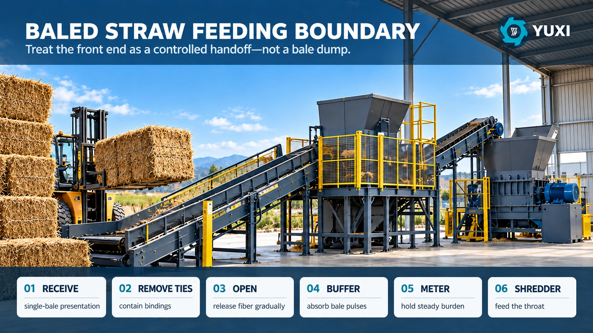
Define the feeding boundary as six material-state changes
The useful question is not “Which conveyor feeds a straw bale?” It is “What condition must the material be in before the next piece of equipment receives it?” That change-of-state approach exposes missing functions early. A conveyor can move a whole rectangular bale reliably and still be a poor metering device after the bale opens. Likewise, a bale opener can decompact fiber successfully while sending a surge that the shredder cannot absorb.
| Front-end function | Material before | Required condition after | Evidence to request |
|---|---|---|---|
| Bale receiving | Delivered bales with supplier and storage variability | Identified, oriented and presented one at a time or in a controlled queue | Bale dimensions, mass range, condition, rejection route |
| Binding control | Compressed bale restrained by twine, strap or wire | Bindings accounted for and prevented from becoming an uncontrolled process contaminant | Expected count/type, recovered count, downstream escape checks |
| Bale opening | Dense coherent package | Fiber released progressively rather than as one slug | Opening rate, peak downstream level, visible clump size |
| Surge buffering | Intermittent loose-straw release | Usable working inventory between low and high levels | Working mass, drawdown time, bridge events, dead zones |
| Metering | Variable loose bulk material | Repeatable burden matched to shredder demand | Speed trend, feed-rate percentiles, starvation and high-load exposure |
| Shredder infeed | Controlled loose straw | Stable engagement without recurring wrapping or overload | Load trend, reversals, interventions, retained fiber after run |
For crop-wide comparisons of moisture, contamination and presentation, the agricultural waste recycling line article is the broader reference.
Do not let the bale clock become the shredder clock
Bales arrive as discrete events. The shredder consumes material continuously. If those two clocks are mechanically coupled, every delay at the forklift, tie station or opener becomes a starvation event, and every fast release becomes a load spike. The engineering purpose of the buffer is therefore not “storage.” It is decoupling.
During trials, divide the stable run into short, consistent intervals and compare the metering and shredder-load traces. Three practical indicators are more revealing than one average throughput number:
- Starvation share = time the feed signal remains below the agreed low-load threshold ÷ running time.
- High-load exposure = time the shredder load remains above the agreed high working band ÷ running time.
- Feed spread = the p90 interval feed rate compared with the p10 interval feed rate during the same stable window.
These are project metrics, not universal acceptance limits. If a different opener sequence, buffer working band or metering control reduces starvation and high-load exposure without reducing accepted output, the front end has become more stable even before a motor or cutter is changed.
Singulate and stabilize the bale before the bindings are released
The tie station is where a transport package loses its restraint. A damaged, weathered or loosely stacked bale can change shape as soon as tension is removed. That is why the line should present a known bale orientation and keep the package controlled through the binding step rather than treating twine removal as an informal manual task beside a moving conveyor.
Build the work sequence around four questions: Can one bale be positively identified? Is the bale stable at the tie-removal point? Where do removed bindings go immediately? What happens to a bale that is broken, moldy, contaminated or too deformed to enter the normal opening route? The answers affect floor space, guarding, reject-lane design and cycle time.
OSHA requires machine guarding where operators can be exposed to ingoing nip points, rotating parts and other machine hazards.3 Its hazardous-energy standard covers servicing activities such as cleaning and unjamming where unexpected startup can injure employees.4 The exact guarding, access and energy-control design must be completed for the installed equipment and site.
Turn binding removal into a measurable control point
Twine and wire are small compared with the bale, but they have an outsized effect on wrapping, maintenance and output contamination. State the binding types that the line must handle and define how they are accounted for.
Expected bindings = bindings confirmed present before tie removal.
Reconciled bindings = bindings recovered at the designated station + binding pieces recovered at the approved downstream inspection point.
Unreconciled bindings = expected bindings − reconciled bindings.
Count is often more useful than mass because several light pieces of twine can create a wrapping problem without materially affecting the mass balance. Any positive unreconciled count should be recorded as an exception and investigated; it should not be closed simply by labeling the binding “missing.” If a binding is already absent or damaged when the bale arrives, record it separately during receiving inspection as missing on arrival. For wire-bound bales, record both count and the recovery route. For plastic twine or netting, add a visual check at the opened material because small fragments may remain even when the main lengths are collected.
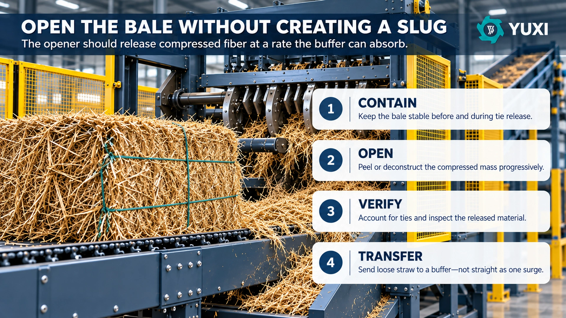
Open the bale progressively instead of asking the shredder to absorb a slug
A bale opener and a primary shredder can overlap mechanically, but their process duties are different. The opener should break the coherence of the package and release material at a controllable rate. The shredder should receive a burden it can engage repeatedly. If a whole compressed face collapses into the chamber at once, the front end has failed even if the machine eventually clears the material.
Watch the material immediately after the opener. Long coherent slabs mean insufficient deconstruction. A cloud of very short fiber and dust can mean the opening stage is doing unnecessary size reduction. Large alternating piles and empty gaps mean the release is not being buffered. The desired condition is loose enough to flow and inspect, but not pulverized simply to make it easier to convey.
If the project still needs to decide where coarse shredding ends and fine grinding begins, use the biomass shredder vs hammer mill comparison. Feeding equipment should not be forced to compensate for a downstream particle-size decision.
Size the buffer from usable working mass, not hopper volume
Loose straw can bridge, form rat holes, leave dead corners and expand after decompaction. What matters is the mass that can be repeatedly drawn between normal low and high operating levels without manual intervention.
Calculate the working inventory from measured loose-straw bulk density during a representative trial. Then convert it into time:
Buffer protection time (min) = usable working mass ÷ downstream mass demand × 60
Use the lowest credible loose-straw bulk density for the volume check, because that is when the hopper fills fastest for a given mass. Then verify the densest or dampest accepted condition for discharge torque and compaction. The same hopper can be volume-limited on very light dry straw and discharge-limited on damp, compressed fiber.
Do not use the full geometric volume in the calculation. Deduct the zone below the low-level setpoint, headspace needed for controlled filling, areas that cannot discharge reliably, and any clearance needed around agitators or level instruments. A supplier should state both gross volume and working mass under the assumed bulk-density range.
Specify low, high and high-high as process states
- Low: enough material remains to avoid immediate starvation while the next bale is being prepared.
- Normal working band: the metering device can draw a consistent burden without compacting the upper inventory.
- High: upstream opening should slow so the buffer can recover.
- High-high: upstream bale release should stop in the designed sequence before material piles into a transfer or guard.
Meter from feedback, not from one fixed conveyor speed
Open-loop feeding assumes that the same belt or chain speed always carries the same mass. Straw does not behave that way. Layer thickness, orientation, loose bulk density and moisture change the actual burden. The metering speed should therefore be adjustable and coordinated with process signals such as buffer level and shredder load.
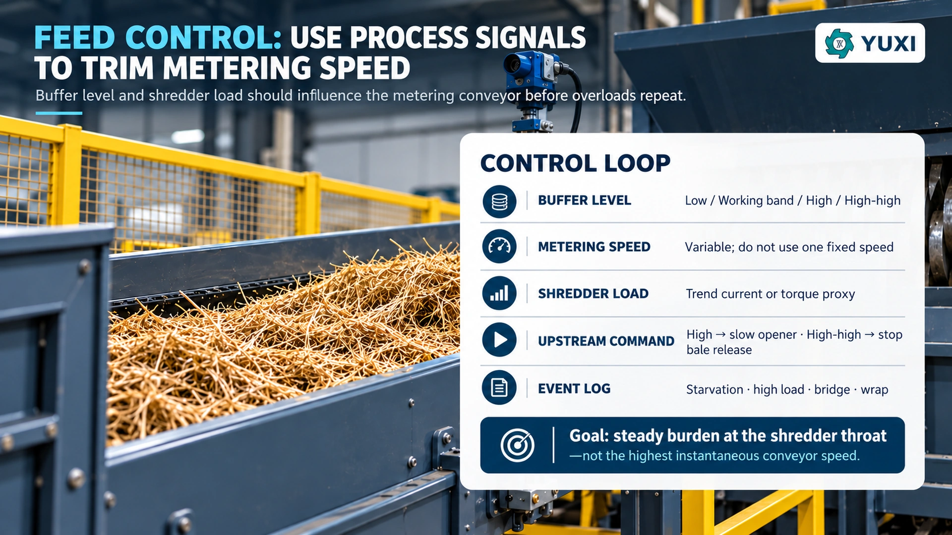
| Observed condition | Preferred process response | Evidence to trend |
|---|---|---|
| Buffer approaching high level | Reduce or pause opener output while metering continues normally | Level, opener command, metering speed |
| Shredder load rising above working band | Trim metering speed before relying on a full overload reversal | Motor current/torque proxy, belt speed, duration above band |
| Repeated reversals in a short period | Stop fresh feed and investigate the recurring cause under the approved procedure | Reversal count, feed condition, bridge/wrap inspection |
| Buffer near low level | Call for the next bale/opening cycle while preserving enough inventory for smooth feed | Low-level duration, starvation time, upstream delay cause |
| Downstream discharge unavailable | Stop upstream feed in the defined sequence so inventory does not stack against a stopped conveyor | Permissives, stop sequence, retained material |
This is a process-control concept, not a substitute for a machine safety control design. Safety functions, emergency stops, guarding interlocks and restart logic must be engineered and validated separately.
Choose conveyor duty by material state
Whole bales and opened straw are different bulk solids. A receiving conveyor needs to accept the largest and heaviest bale, withstand loader placement or transfer loads, maintain alignment and present the bale to the next station. A loose-straw conveyor needs to prevent rollback, edge loss, wrapping and unstable burden depth.
| Material state | Typical duty | Design checks |
|---|---|---|
| Complete rectangular bale | Chain/slat or robust belt receiving conveyor | Bale width, maximum mass, impact at placement, stop/start under load, bale alignment |
| Opened loose straw | Live-bottom, walking-floor, belt or other positive-discharge transfer | Bridge tendency, sidewall friction, exposed shafts, low-density volumetric capacity |
| Metered loose layer | Variable-speed belt/chain feeding shredder | Bed-depth control, speed range, clean return path, load feedback |
| Very short or dusty fraction | Enclosed transfer where justified | Dust containment, cleaning access, buildup and ignition-source review |
For corn-stover projects, the feed can include stalks, leaves, husks and cobs that change both density and flow behavior. The corn stalk recycling line guide is useful when the bale is not a uniform straw package.
Prevent bridging with geometry before adding horsepower
Long dry fibers can span a hopper opening while the material below continues to discharge, creating a stable bridge that is invisible from a level sensor mounted in the wrong place. Damp straw can compact against sidewalls. Loose fiber can catch on protrusions, bearing housings or exposed shaft ends. These are flow-path problems.
Inspect the front end as one continuous path. Look for sudden reductions in cross-section, ledges at chute transitions, narrow points created by guards or structural steel, transfer gaps where long fibers can hook, low-speed rollers that accumulate wrapping, and flat hopper zones that depend on gravity even when the material does not flow freely. The solution may be a wider throat, steeper or smoother transition, live-bottom extraction, scraper, different transfer height or a changed bale-opening pattern.
Use a five-point bridge investigation
- Photograph the first physical location where material stops moving—not only the final machine that alarms.
- Record bale source, moisture, fiber condition and binding type for the event.
- Check whether the bridge formed during a full-buffer state, low-buffer state or immediately after a bale release.
- Measure how much inventory was above the restriction and whether the metering device was drawing evenly across its width.
- Change one controlled variable, rerun representative material and compare the event rate.
Repeated bridging should not become a normal manual task. Cleaning or unjamming work can expose employees to hazardous motion, so the site needs an energy-control procedure that matches the installed conveyor, opener and shredder system.4
Design the layout for reject handling and maintenance, not only flow arrows
A front-end layout can look compact on a process diagram and still fail in daily operation. The bale queue needs enough space to keep forklift traffic from blocking the tie station. Off-spec bales need a visible hold route that does not cross the normal infeed. Binding waste needs a container that can be changed without stopping or entering a hazard zone. The opener and buffer need access for inspection and planned clean-out, and wear parts need removal space.
Separate routine operator access from maintenance access. A viewing platform or camera can make the process observable without encouraging entry near moving equipment. Where dry straw produces dust, access platforms, cable trays and horizontal steelwork can become accumulation surfaces. OSHA’s revised combustible-dust program addresses workplaces that generate or handle combustible dusts, including finely divided organic materials that can present fire, flash-fire, deflagration or explosion hazards.5 Dust collection, housekeeping, ignition control and fire/explosion protection require a site-specific hazard assessment.
Use bale data to select the control recipe
FCIC research emphasizes that biomass properties vary and that this variability affects integrated feeding and preprocessing.2 The practical response is to stop treating all bales as one feed grade. A simple receiving record can map common bale states to tested front-end recipes.
| Bale condition | Front-end concern | Recipe decision |
|---|---|---|
| Light, dry, springy bale | Rapid expansion and low loose bulk density | Limit opener surge; confirm volumetric buffer capacity |
| Dense, tightly compressed bale | High release load and possible large coherent slabs | Reduce opening aggression and verify buffer high-level response |
| Damp outer layers | Compaction, clumping and sidewall friction | Use validated damp-material feed speed and inspect for discharge buildup |
| Damaged or partly collapsed bale | Unpredictable tie tension and poor singulation | Divert to the approved abnormal-bale handling route |
| Mixed or uncertain binding | Wrapping and contamination risk | Increase verification or hold until the binding-control route is confirmed |
Keep the record short enough that operators will actually use it: supplier or field source, bale format, approximate mass, moisture group, binding type, visible damage, contamination status and the selected recipe. If the project later sends the prepared straw to pellet production, the biomass pretreatment for pellet production guide covers the separate drying and fine-grinding boundary.
Run a feeding FAT that exposes the bottleneck
The factory acceptance test should prove that the complete feeding section can sustain a documented operating window with representative bales and that unstable conditions are visible in the data.
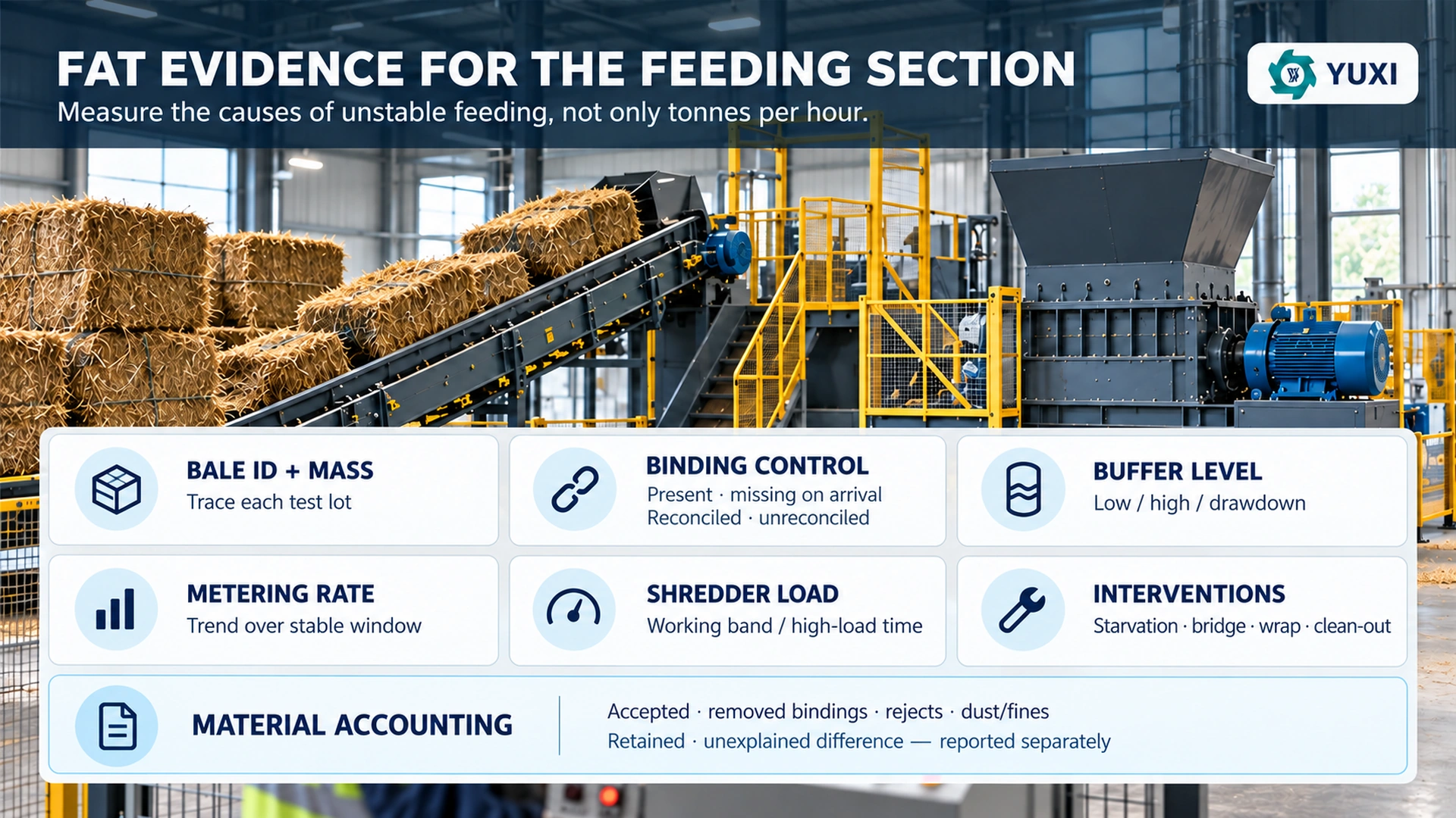
Minimum evidence set
- Input: bale ID, source, dimensions, individual mass where practical, moisture group and binding type.
- Binding control: bindings confirmed present before tie removal, bindings recorded as missing on arrival, bindings recovered at the designated station, downstream binding pieces, reconciled count and any unreconciled count reported separately.
- Buffer: level trend, high/high-high events, low-level time and visible bridging or dead-zone observations.
- Metering: conveyor speed or command, interval feed-rate estimate and burden condition.
- Shredder response: current or torque proxy, reversals, sustained high-load time and longest starvation periods.
- Interventions: bridges, wraps, manual feed corrections, abnormal-bale diversions and clean-out time, each coded by cause.
- Material accounting: accepted downstream material, removed bindings, rejected material, captured dust/fines or cleanup material, retained material and unexplained difference, each reported separately.
Use time-in-band acceptance, not one peak capacity number
For the feeding section, a good guarantee can combine mass throughput with stability. Example acceptance language might require the agreed as-received mass over the full test window, no unresolved binding carryover, a maximum number of manual interventions per 100 bales, a stated maximum share of time above the shredder high-load band, and a stated maximum starvation share after the line has reached the normal operating window.
The existing straw recycling line article covers the wider line, dry-mass capacity and downstream sizing. For this feeding FAT, keep the boundary deliberately narrower so a good shredder result cannot hide poor bale handling.
Tune commissioning in an order that preserves evidence
During commissioning, change one part of the feed-control chain at a time. First confirm that the receiving and binding route handles the approved bale range without abnormal intervention. Next establish an opener rate that keeps the buffer inside its usable working band. Then tune the metering speed range to hold the shredder near its normal working load. Only after that should the team fine-tune load-based trim, level alarms and restart sequencing.
Keep before-and-after trends for each change. If opener speed, buffer setpoints, metering speed and shredder controls are all altered in one run, the team may obtain a better result but will not know why. A short engineering log—change, reason, lot ID, before result, after result—creates repeatable recipes for the next harvest or supplier.
Front-end RFQ questions that reveal missing scope
- What bale formats, minimum/maximum dimensions and individual mass range are included?
- Which binding types are accepted, and where are they removed, contained and verified?
- How is a damaged or partly collapsed bale diverted without obstructing the normal line?
- What equipment deconstructs the bale before metering, and how is opener output adjusted?
- What is the buffer’s gross volume, usable working mass and assumed loose-straw bulk-density range?
- What discharge device prevents bridging, and what evidence supports it on the longest and dampest accepted fibers?
- Which signals trim the metering conveyor, and which signals only alarm or stop the line?
- How are repeated reversals, wraps and bridge events logged and differentiated?
- Which guards, emergency stops and hazardous-energy isolation points are included in the supplier scope?
- Which dust-collection and fire-protection boundaries are included, and which require site engineering?
- What FAT data will be exported: buffer level, metering command, shredder load, stops, alarms and event history?
- How will accepted material, rejected material, removed bindings, captured dust/fines, retained material and unexplained difference be reported separately?
Quick decision rule for a stable baled-straw infeed
If whole bales arrive faster than they can be inspected and strippedImprove staging, singulation or parallel tie handling before increasing shredder capacity.
If the opener creates alternating piles and gapsReduce the release pulse or increase usable buffer decoupling.
If the buffer stays full but the shredder starvesInvestigate bridging, dead zones and extraction geometry.
If the shredder repeatedly overloads with a normal buffer levelTrim metering rate and inspect fiber engagement before adding motor power.
If bindings appear downstreamTreat the tie station as a failed control point and close the accountability gap.
If short-run throughput is good but shift output is poorRank downtime by starvation, bridge, wrap, abnormal bale and restart cause.
Configure the feeding section around representative bales
Send bale photos and video, normal and maximum dimensions, individual mass range, moisture range, binding type, damaged-bale frequency, visible contamination, required tonnes per hour, workshop layout and the downstream machine that receives the straw. Those details are enough to start defining a receiving, opening, buffering and metering concept that can be tested rather than guessed.
FAQ
Can a whole straw bale be fed directly into an industrial shredder?
Sometimes a machine can accept a whole bale, but that does not prove stable production. A compact bale can release as one dense slug, overload the throat, carry bindings into rotating equipment, or flood the downstream conveyor. A more controllable front end normally singulates the bale, accounts for the ties, opens the compressed structure, buffers the loose straw and meters the shredder.
How large should the buffer be after a straw bale opener?
Do not size it from gross cubic metres alone. Define the working mass between the low and high operating levels at the lowest realistic loose-straw bulk density, then check how many minutes of downstream demand that working mass protects. The hopper also needs a discharge method that prevents dead zones and bridging; a large vessel with poor live-bottom behavior is not a useful buffer.
Is a chain conveyor or belt conveyor better for baled straw?
Use the conveyor type that matches the material state and duty. A slat or chain conveyor can be well suited to whole bales and demanding receiving service, while a belt may provide a cleaner, more observable surface for controlled transfer. Loose opened straw can require a live-bottom bin, walking floor or other positive-discharge arrangement before the metering conveyor.
Should bale twine or wire be removed before the opener?
The project should have a defined binding-control method before production. Where bindings can be removed before opening, provide a guarded work or automatic removal station, a collection route and a verification record. If a process intentionally handles a binding type through an opening stage, that condition must be specifically engineered, tested and controlled rather than assumed to be harmless.
How do you prove that a baled-straw feeding line is stable?
Run representative bales through the complete front end and trend the evidence over the same time window. Record bale identity and mass, binding recovery, buffer level, metering speed, shredder load, starvation time, high-load exposure, bridges, wraps, reversals and manual interventions. Use percentiles or time-in-band results instead of quoting only the best short-term tonnes-per-hour figure.
Configure the feeding section around representative bales
Send bale photos and video, normal and maximum dimensions, individual mass range, moisture range, binding type, damaged-bale frequency, visible contamination, required tonnes per hour, workshop layout and the downstream machine that receives the straw. Those details are enough to start defining a receiving, opening, buffering and metering concept that can be tested rather than guessed.
References
- DOE: feedstock logistics.
- DOE: feedstock variability.
- OSHA: machine guarding.
- OSHA: energy control.
- OSHA: combustible dust.
Online Message